Important: These three pieces must be free of
any rust protection, or lubricant. Any grease or
residue in these areas can cause the pieces to
separate, creating a safety hazard and potential
damage to the tool.
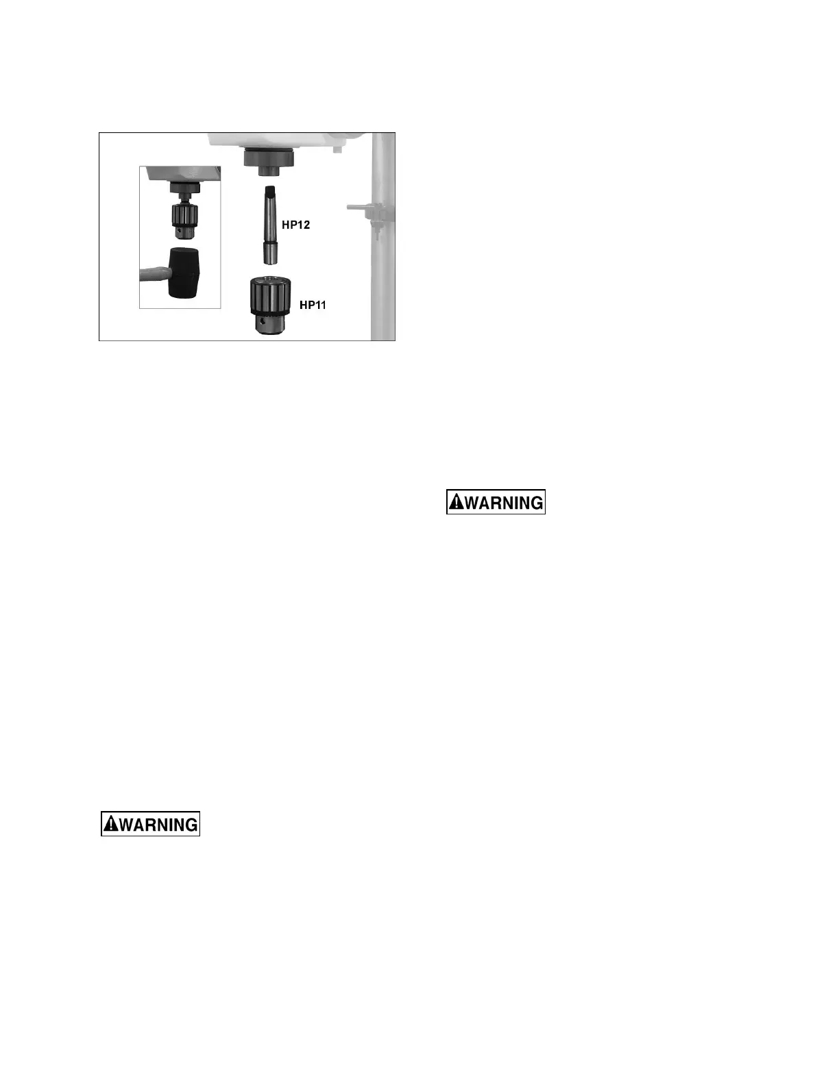
Figure 12
19.
Lower the table out of the way of the spindle
area.
20. Slide arbor (HP12) up into
spindle. Turn the
arbor as you push it, until the tang engages
the
s
lot in the spindle.
21.
Push chuck (HP11) onto arbo
r.
22.
Twist the chuck to completely retract the chuck
jaws if they are exposed.
23.
Use a rubber mallet, or a steel hammer agains
t
a bloc
k of wood, to sharply tap the bottom of
the
c
huck two or three times to seat the chuck/
arbor
a
ssembly. Note: Do not use a steel faced
hammer directly against the chuck.
6.6 Chuck key and wrench storage
The chuck key can be stored in the clip on the collar
(see Figure 8).
The table locking wrench has a magnetic disc
attached, and can be stored on any metal surface.
Do not store in an area near the worktable, or
where the wrench could vibrate off into moving
parts.
7.0 Electrical connections
Electrical connections must be
made by a qualified electrician in compliance
with all relevant codes. This machine must be
properly grounded to help prevent electrical
shock and possible fatal injury.
The JDP-15F/15B drill press is rated at 115V power
only, and comes with a plug designed for use on a
circuit with a grounded outlet that looks like the one
pictured in A, Figure 13.
Before connecting to power source, be sure the
switch is in off position.
It is recommended that the drill press be connected
to a dedicated 15 amp circuit with circuit breaker or
fuse. If connected to a circuit protected by fuses, use
time delay fuse marked “D”. Local codes take
precedence over recommendations.
7.1 Grounding instructions
This machine must be grounded. In the event of a
malfunction or breakdown, grounding provides a
path of least resistance for electric current to reduce
the risk of electric shock. This tool is equipped with
an electric cord having an equipment-grounding
conductor and a grounding plug. The plug must be
plugged into a matching outlet that is properly
installed and grounded in accordance with all local
codes and ordinances.
Do not modify the plug provided - if it will not fit the
outlet, have the proper outlet installed by a qualified
electrician.
Improper connection of the equipment-grounding
conductor can result in a risk of electric shock. The
conductor with insulation having an outer surface
that is green with or without yellow stripes is the
equipment-grounding conductor. If repair or
replacement of the electric cord or plug is
necessary, do not connect the equipment-grounding
conductor to a live terminal.
Check with a qualified
electrician or service personnel if the grounding
instructions are not completely understood, or if
in doubt as to whether the tool is properly
grounded. Failure to comply may cause serious
or fatal injury.
Use only 3-wire extension cords that have 3-prong
grounding plugs and 3-pole receptacles that accept
the tool's plug.
Repair or replace damaged or worn cord
immediately.
This tool is for use on a nominal 120-V circuit, and
has a grounded plug that looks like the plug
illustrated in sketch A in Figure 13. A temporary
adaptor that looks like the adaptor illustrated in
sketches B and C may be used to connect this plug
to a 2-pole receptacle as shown in sketch B if a
properly grounded outlet is not available. The
temporary adaptor should be used only until a
properly grounded outlet (sketch A) can be installed
by a qualified electrician. The green colored rigid
ear, lug, or the like extending from the adaptor must
be connected to a permanent ground such as a
properly grounded outlet box cover. Whenever the
adaptor is used, it must be held in place by a metal
screw.
In Canada, the use of a temporary adaptor is not
permitted by the Canadian Electrical Code, C22.1.

 Loading...