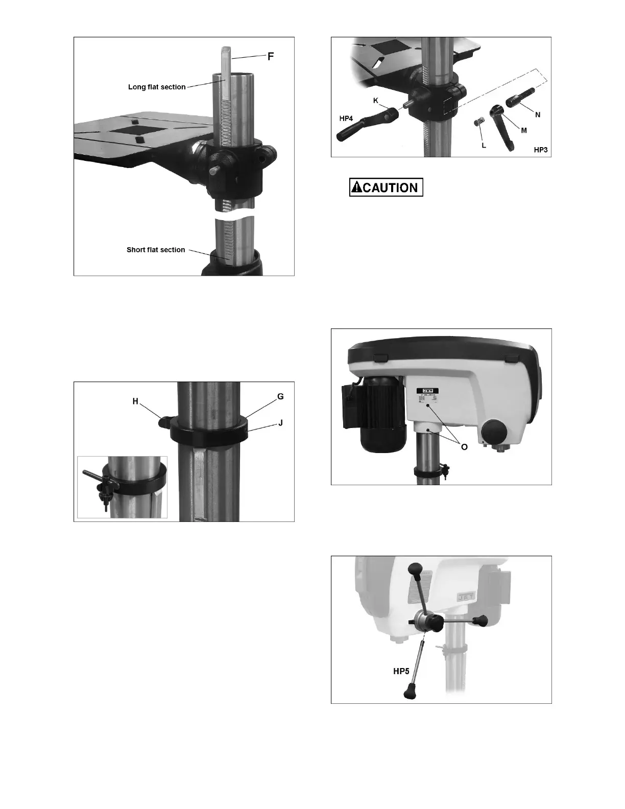
Figure 7
9.
Place stop collar (G, Figure 8) onto column
and
s
lide it down over top end of rack. Or
ient the
s
top collar so that chuck key holder (H) is
in
des
ired position around the column
.
10.
Tighten set screw (J) with a 4mm hex key.
11.
Push chuck key into holder (ins
et, Figure 8)
Figure 8
12.
Slide table elevating handl
e (HP4, Figure 9)
onto protruding s
haft of worm. Make sure the
set screw in the handle aligns with the flat on
the worm shaft.
13.
Tighten set screw (K) in table elevating handle
with 4mm hex key.
14.
Mount column locking handle (HP3, Figure 9) to
rear of table bracket. The quickest way to install
this is to remove the handle by unscrewing the
screw with its spring (L). Insert the bolt (N) in
to
the table brac
ket hole, then reinstall handle (M
),
s
pring and scr
ew (L).
Note: The loc
king handle (HP3) is adjus
table.
To repos
ition, pull out on the handle and rotate
it, then release it, making sure it reseats itself
on the bolt head.
Figure 9
The head assembly is
heavy! To avoid injury and/or damage to
equipment, lift the head onto the column
only with additional assistance!
15.
With the aid of a second person, carefully lift the
head assembly and place it onto the column
.
Slide head down as
far as it will go. Rotate head
assembly until the sides of the belt cover are
parallel with the sides of the base.
16. Tighten the two set screws (O, Figure 10)
with
a 5mm
hex key until they are s
nug.
Figure 10
17.
Install three downfeed handles
(HP5, Figure 11)
into hub by
screwing them in completely. A flat
is provided on each handle for a 9mm wrench
or pliers to help tighten if nee
ded.
Figure 11
18.
Thoroughly clean spindle, arbor and chuck
(Figure 12) with a soft rag and solvent, such as
mineral spirits.
 Loading...