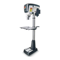
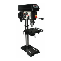
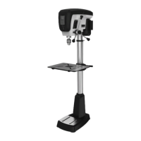
6.4 Location
The drill press should be placed in a dry area, with
a level floor and good lighting. Provide enough
space around drill press to allow for operations and
any adjustments or servicing.
6.5 Assembly
Do not connect drill press to
power source until machine has been fully
assembled.
1.
Place the base upon a level floor. It may
be
s
ecured to the floor with lag screws (not
provided) through the two holes in the base.
Refer to Figure 1 for hole spacing.
If you do not wish permanent attachment to the
floor, the drill press can be bolted to a plyw
ood
panel whic
h will serve as an expanded base
and further stabilize the machine. Use a high
grade of plywood (not particle board) at least
3/4" thick. It should be large enough to prevent
vibration, sliding or moving of drill press during
operation. Do not use a mobile base with this
mach
ine.
2.
Make sure the set screw (Figure 4) is
tight
agains
t the column. Tighten further if
needed,
us
ing a 5mm hex key.
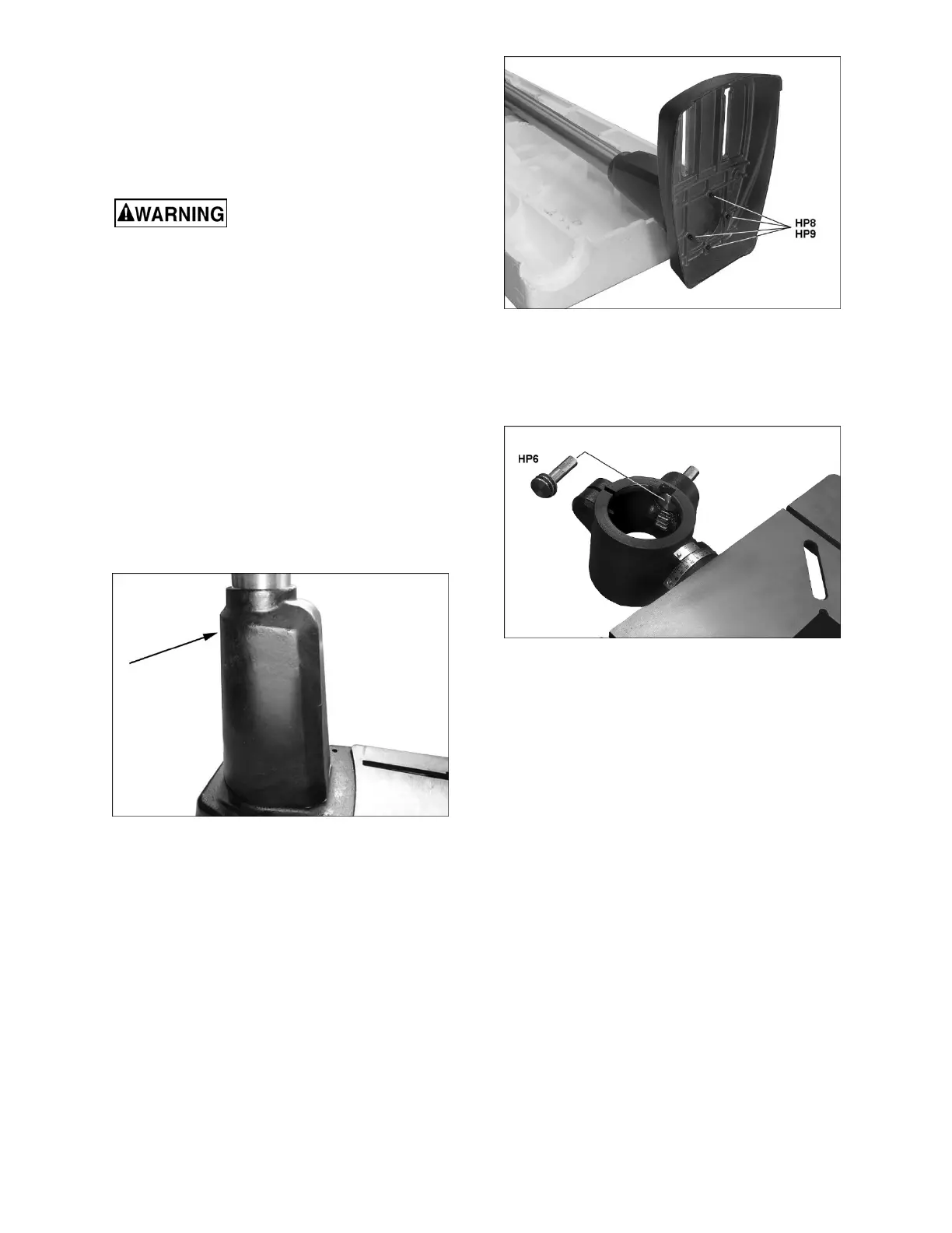
Figure 4
3.
Lay the column assembly down on an elevated
surface (such as the included polystyrene
packaging). Attach base to column foot with
four M8x50 socket head cap screws and f
our
8mm
flat washers (HP8/HP9, Figure 5), using a
6mm hex key. NOTE: Align base and foot so
that their edges are flush.
4. Tighten
screws firmly
.
Figure 5
5.
Set column assembly upright
.
6.
Insert the worm shaft (HP6, Figure 6) through
the hole in the table bracket as far as it will go,
meshing the worm with the teeth on the gear.
Figure 6
7.
Position rack (F, Figure 7) into the slot in table
bracket. The longer flat portion of the rack
should be at the top, the short flat portion at the
bottom. Mesh the rack teeth with the worm gea
r
in the table brac
ket.
8.
With the aid of a second person, hold the rack
in the slot, while setting the table bracket ov
er
the top of
the column. Then slide table bracket
and rack together down the column
until the
lower end of
the rack rests in the lip of
the
holder, as
s
hown in Figure 7.
 Loading...