Figure 18
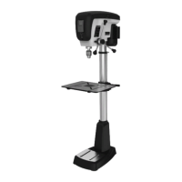
8.7 Changing spindle speeds
Refer to Figure 19.
1.
Disconnect machine from power source
.
2.
Open belt cover. Loosen knob (A, Figure 19)
and pull tensioner (B) away from belt to releas
e
tens
ion.
3.
Consult speed chart (C) and position belts
accordingly.
Note: The center pulley can be pushed to front
or back to release tension to either belt, as
needed. When front belt is correctly positioned,
push center pulley backward to tighten front belt
and allow rear belt to slide onto the pulleys
.
4.
Make sure belts are properly seated in the
grooves of each pulley.
5.
Push tensioner (B) into belt and tighten knob
(A). Clos
e hood.
Figure 19
8.8 Depth stop
The depth stop is used for repetitive drilling of holes
of identical depth.
Depth stop can be established by one of two
procedures:
Method #1:
Refer to Figures 20 and 21.
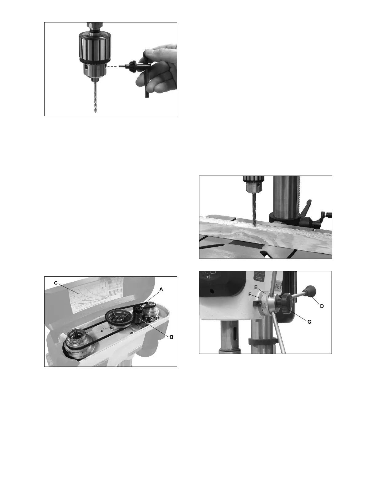
1.
Loosen lock handle (G, Figur
e 21).
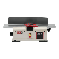
2.
Use downfeed handles (D, Figure 21) to lower
the bit until it just contacts the top surface of
workpiece, as shown
in Figure 20.
3.
Hold downfeed handle in position, and rotate
scale ring (E, Figure 21) to zero. This sets
the
work
piece surface as your zero referenc
e point.
4.
Move workpiece out from un
der bit, and rotate
downf
eed handle to lower bit until sca
le ring (E)
reads
your desired depth.
5.
Hold downfeed handle in this position, and
rotate lock ring (F) counterclockwise as far as
it
will tur
n. You should be able to feel and hear
when the lock ring reaches the end of its
rotation.
6.
Tighten lock handle (G
).
7.
The bit can now be repeatedly
lowered to the
pre-s
et depth using the downfeed handles.
8.
To release the depth stop, loosen lock handle
(G).
Figure 20
Figure 21
M
ethod #2:
Refer to Figures 22 and 23.
1.
Mark the desired depth of cut on the side of the
workpiece (Figure 22).
2.
Use downfeed handle (D, Fi
gure 23) to lower
the bit to the
mark. Hold downfeed handle in
position.
3.
Rotate lock ring (F) counterclockwise as far as
it will turn. You should be able to feel and
hear
when the loc
k ring reaches the end of its
rotation.
 Loading...