13
Laser Adjustment
The Laser Assembly has been installed and preset at
the factory. It should, however, be checked and
adjustments made, if necessary, before operating the
drill press. It should also be rechecked periodically,
as constant machine use may cause it to become
misaligned. Make verifications and align as follows:
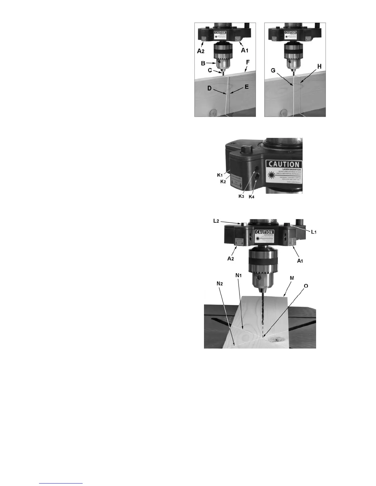
Referring to Figure 11:
1. Take a length of board (F) and draw a
perpendicular line (E) on one side using a square.
2. Place a small drill bit (C) in the chuck (B), then
place the board (F) on the table on edge against
the drill bit (C) with the marked line side facing
toward the laser to be aligned (A
1
in this case).
Important: The table should be in horizontal
position and locked.
3. Connect power to the drill press and turn on
the laser using the button at the front of the
drill press head.
Two parallel laser markings will appear that should
look like G and H in Figure 11 – the distance
between the lines will vary with board thickness;
however, the lines must be parallel to each other
and the marked line (vertical alignment).
If alignment is necessary:
Vertical Alignment (refer to Figure 11)
5. Make slight adjustments to four setscrews
(K
1-4
, Fig. 12) and move the board (F) from
side to side as required until the laser light (D)
lines up with the board marking (E).
6. Tighten all four setscrews so they are snug
against the laser housing, but do not over tighten.
Verify that the laser light is still lined up with
board marking.
7. Adjust the other laser in the same manner.
Two resulting parallel laser markings should look like
G and H in Figure 11 – the distance between the lines
can vary but must be parallel to each other and the
marked line.
Cross Hair Alignment (refer to Figure 13)
8. Place board (M) flat on the table. Do not allow
the board to move from this position; use
clamps if needed. Bring the bit down until it
leaves a slight perforation in the board (O)
then raise it back up.
9. Turn on the laser to check if the cross-hairs
intersect at the perforation.
If adjustment is required:
10. Choosing first one laser (A
1
in this case),
loosen two setscrews on the same side (either
side) of the laser housing equal amounts about
1/4 turn or less.
Figure 11
Figure 12
Figure 13
11. Adjust (L
1
) so the laser line (N
1
) crosses the
perforation (O); then retighten setscrews.
12. Adjust the other laser assembly in the same
manner until both laser lines form cross-
hairs (N
1
, N
2
) exactly over the perforation (O)
in the board.
13. Recheck the vertical alignment to insure that
the laser lines did not shift during the
tightening process.
The laser is now calibrated properly and the
location of your holes can be centered at the
crosshairs for accurate drilling.