8
Assembly
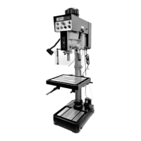
Base and Column Assembly
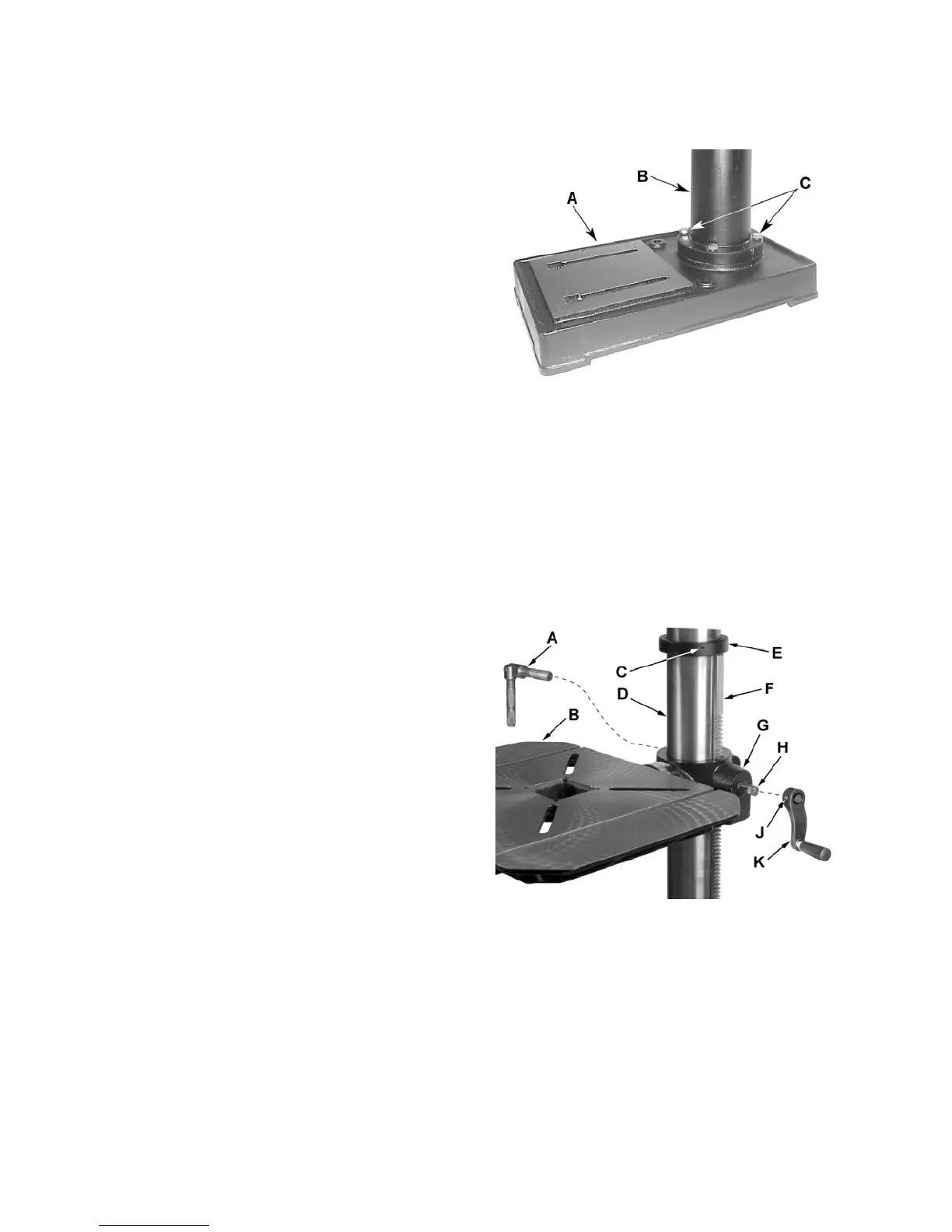
Referring to Figure 1:
1. Place the base (A) on a level floor.
2. Place the column assembly (B) on the base (A)
and align the holes in the column support with
the holes in the base.
3. Using a 17mm wrench, secure the column (B)
with four M10 x 40 hex cap screws (C) to the
base.
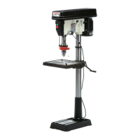
Table and Rack
Referring to Figure 2:
When shipped, the rack ring (E) and rack (F) are
bundled together with the column (D) in plastic
wrap.
1. Remove the wrap and take the rack ring (E)
and rack (F) off the column (D). Note which end
of the rack is up. It must be reinstalled later
with the same side up.
2. Place the rack (F) inside the table bracket (G)
such that the teeth of the rack (F) mesh with
the pinion gear on the end of the table crank
handle shaft (H).
3. Slide the table and bracket assembly (B, G)
together with the rack (F) onto the column (D)
as shown.
4. Slide the rack ring (E) onto the column (D),
placing it so it rests against the rack (F) as
shown and tighten the setscrew (C) with a 3mm
hex wrench.
Table Crank and Column Lock Handles
Referring to Figure 2:
1. Loosen the setscrew (J) on the table crank
handle (K).
2. Slide the handle (K) onto the table bracket
shaft (H).
3. Turn the handle (K) until the setscrew (J) is on
the flat section of the shaft (H) and tighten the
setscrew (J) with a 3mm hex wrench to secure
the handle.
4. Thread the column lock handle (A) into the
back side of the table bracket (G) opposite the
crank handle (G).
Figure 1
Figure 2