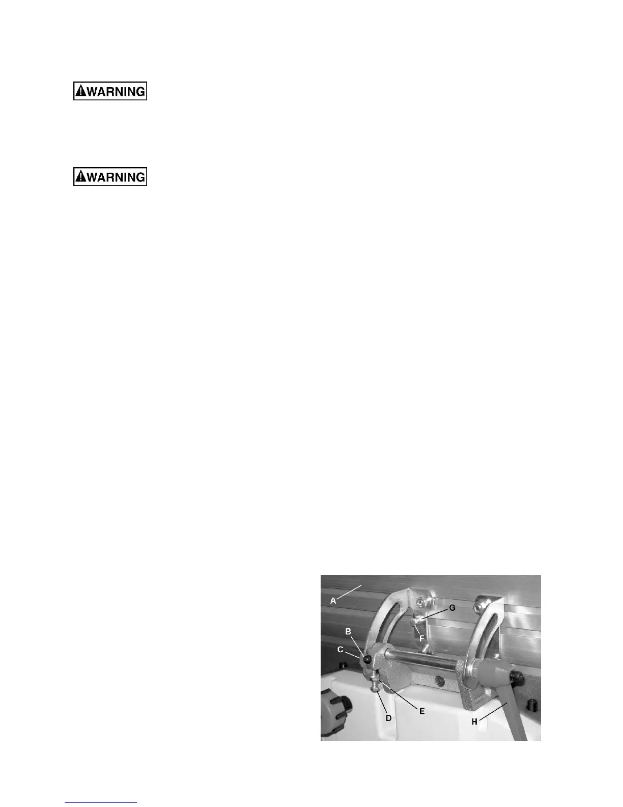
16
Replacing Cutter Knives
Disconnect machine from
power source before making any adjustments.
Failure to comply may cause serious injury.
1. Disconnect machine from the power source.
2. Remove the cutterhead guard.
Cutterhead knives are
dangerously sharp. Use extreme caution when
inspecting, removing, sharpening, or replacing
knives into the cutterhead. Failure to comply
may cause serious injury.
Referring to Figures 16 and 17 (page 15):
3. Turn all six gib lock screws (A) into the lock bar
(B) by turning in a clockwise direction as
viewed from the infeed table (K).
4. Carefully remove the cutter knife (C) and lock
bar (B).
5. Repeat for the remaining knife.
6. Thoroughly clean all surfaces of the
cutterhead, knife slots and lock bars of any
dust or debris.
7. Insert the first replacement knife (C) into the
knife slot, making sure it faces the proper
direction.
8. Insert lock bar (B) and tighten just enough to
hold in place.
9. Repeat for other the remaining blade.
Following installation, the knives must be adjusted
as described in Cutterhead Knive Adjustment on
page 15.
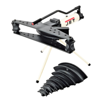
Jointer Fence Adjustment
Referring to Figure 18:
The jointer fence (A) can be adjusted from a full
forward position (90º to table, corresponding to a
scale reading of 0º) to a full back-tilted position of
135 º (scale reading of 45 º).
If setting to maximum positions do not stop the
fence at 0º or 90º, make adjustments as follows:
Fence 90º Adjustment
1. Loosen lock handle (H) and bring fence fully
forward. Using a square, determine if the fence
is 90º to the table.
If adjustment is required:
2. Loosen jam nut (E) and adjust stop screw (D)
in or out until a fence postion of 90º with
respect to the table is achieved.
3. Secure the jam nut (E).
Check the scale indication. If the indicator (C) does
not point to zero:
4. Loosen screw (B), adjust accordingly, then
retighten screw.
Fence 45º Adjustment
Verify that the fence and scale indication is
accurate at 90º as outlined in Fence 90º
Adjustment above.
1. Loosen lock handle (H) and set the fence all
the way back. Using a square, determine if the
fence is 135º to the table.
If adjustment is required:
2. Loosen jam nut (G) and adjust stop screw (F)
in or out until a fence postion of 135º with
respect to the table is achieved. Note: The
screw head stops against the fence mounting
bracket.
3. Secure the jam nut (G).
Figure 18