6
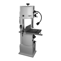
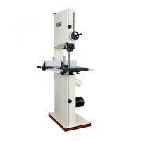
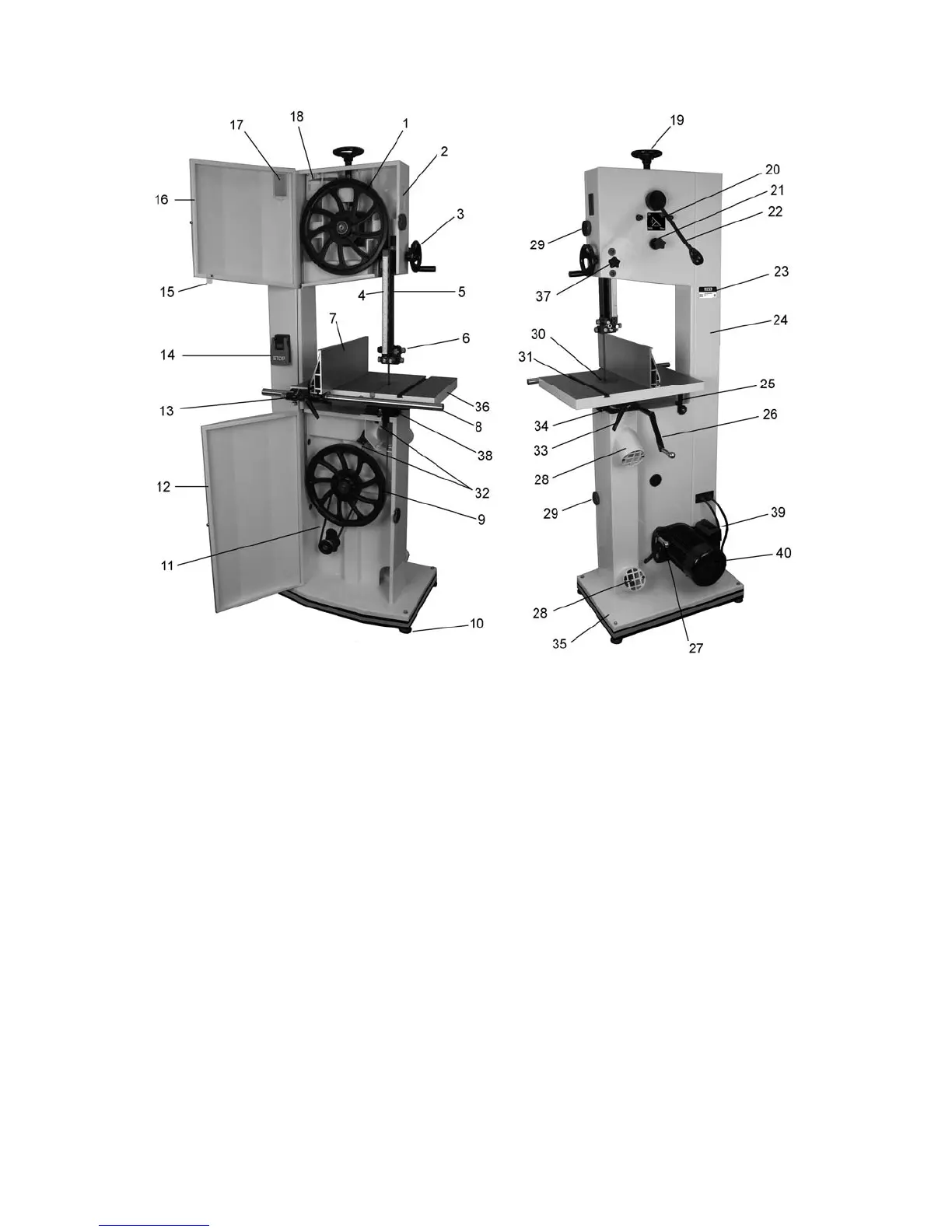
5.0 Features and Terminology
Figure 1
1. Upper wheel
2. Tracking window
3. Guide post handwheel
4. Cutting height scale
5. Guide post
6. Upper blade guides
7. Fence plate
8. Guide rail
9. Lower wheel
10. Leveling screw with foot pad (x4)
11. V-belt
12. Lower door
13. Fence micro-adjustment
14. Start/stop switch
15. Guide post scale indicator
16. Upper door
17. Tension scale window
18. Blade tension scale
19. Blade tension handwheel
20. Direction label (tension release handle)
21. Blade tracking knob
22. Blade tension handle
23. I.D. label
24. Column
25. 90-degree stop
26. Table tilt handle
27. Motor lift handle
28. Dust port (x2)
29. Door lock knob (x2)
30. Table insert
31. Miter slot
32. Brush (x2)
33. Table tilt lock handle
34. Table trunnion
35. Base
36. Cast iron table
37. Guide post locking knob
38. Lower blade guides
39. Motor capacitor box
40. Motor, 1-3/4HP dual voltage
The specifications in this manual were current at time of publication, but because of our policy of continuous
improvement, Walter Meier (Manufacturing) Inc., reserves the right to change specifications at any time and
without prior notice, without incurring obligations.
 Loading...