Bareshaft Pump
13
Flushing the System
With the engine at idle, warming to operating tem-
perature, ush the system of any debris. Flushing the
system prevents any debris from clogging the clean-
ing nozzles and valves which will cause excessive
pressure in the system. Nozzles must be removed
from all equipment during ushing.
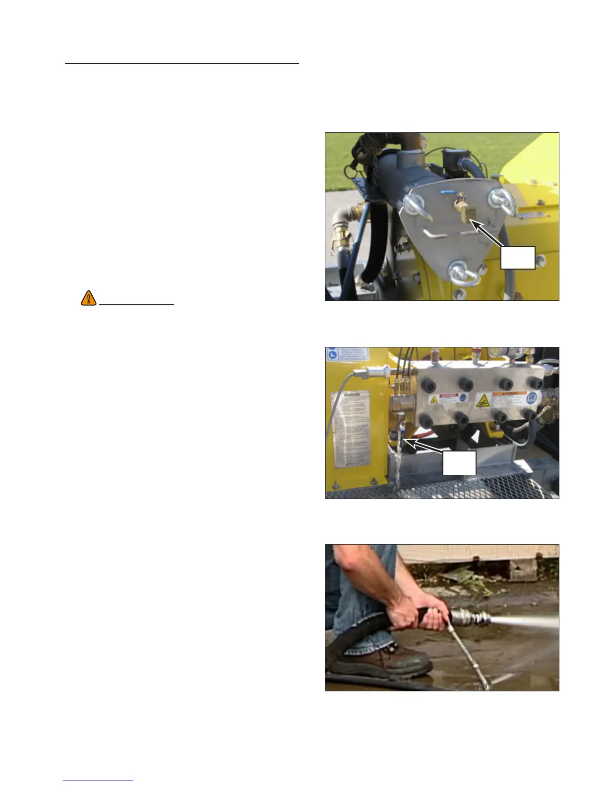
1. If operating at 40K, rst open the bleed valve
(“Figure 6: Secondary Filter Bleed Valve.” on
page 13) and allow any air to purge from the
secondary lter. Once a steady ow of water
exits the lter, close the valve.
2. Open the manifold drain valve. Allow water to
drain from the valve for approximately 5-10
seconds. (“Figure 7: Flushing the Manifold.” on
page 13).
3. Hold the discharge hose stationary (Figure 8).
4. With the manifold free of debris, the engine at nor-
mal operating temperature (160°F (71°C) - 185°F
(85°C)) and at idle speed, engage the clutch.
5. Turn the bypass valve clockwise just enough
to obtain a generous ow of water through the
discharge hose. Allow the hose to ush for
about 30 seconds.
Note: A substantial amount of thrust may occur
at the discharge end while ushing.
6. Decrease ow to the hose by fully opening
(counter-clockwise) the bypass valve. Some
water will continue to ow from the hose.
7. With the engine at idle speed, shift the trans-
mission to Neutral.
8. Connect the control gun (or other equipment
being used) to the discharge hose.
9. With the hose secure and equipment controlled
by another operator, engage the clutch.
10. Turn the bypass valve clockwise to increase
ow through the discharge device(s). Allow the
control gun to ush for about 30 seconds.
11. Reduce the discharge ow by fully opening the
bypass valve.
12. With the engine at idle speed, disengage the
clutch.
WARNING
!
Two operators are required to ush the
discharge hose and equipment. One operator
must be stationed at the unit and the other at
the discharge device.
13. The nozzles can now be installed on the dis-
charge device(s).
14. Before waterblasting, adjust the lubrication line
needle valves, if equipped. Refer to “Checknig
the Water Lubrication System” on page 14 .
Figure 8: Flushing the Discharge Hose.
Figure 6: Secondary Filter Bleed Valve.
Bleed
Valve
Figure 7: Flushing the Manifold.
Drain
valve

 Loading...