33
RS485 or GPRS communication interface (optional)
Grounding terminal(Grounding screw on the right side of
inverter case)
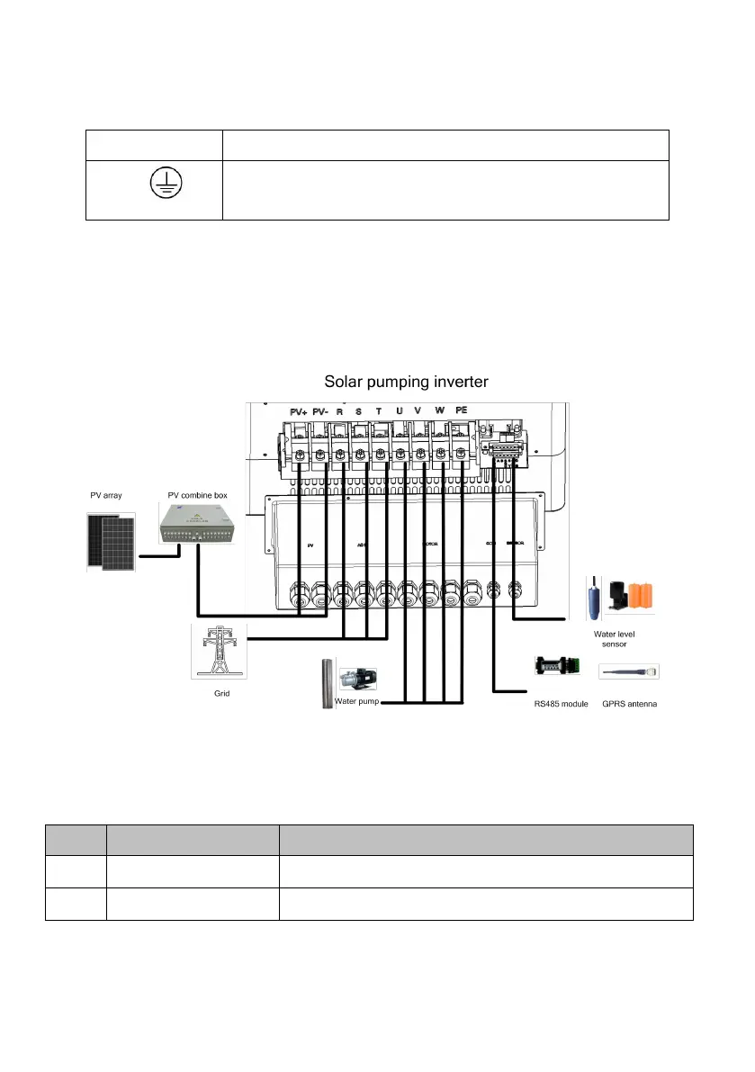
6.2 Schematic Diagram of Electrical Connection
Figure 6-2 is the schematic diagram of electrical connection among PV arrays,
Solar Pump Inverter and three phase AC pump. Water level sensor and
communication interface shall be connected if needed.
Figure 6-2 schematic diagram of electrical connection of photovoltaic pump
inverter
Table6-2 Equipment list of Solar pump system
The max. Voc of each string is 880V.
Power grid, diesel generator or other AC input