138
“FULL DIAGNOSTIC”
6-73
6-72.a
1
2
53
1
4
2
6-72.b
6.5.1 “FULL DIAGNOSTIC” Menus
This section sets out the specific functions of the “FULL
DIAGNOSTIC” mode and
only the Menu items that
refer to this mode.
For information about the other items and icons, refer
to the basic chapter “4.1”, as well as the Automatic
Modes specifications described earlier.
The “Optima Full Diagnostic” function selection items
are already displayed from the “BALANCE WITH
RUNOUT” Automatic Mode. Their use is only possible
in the “FULL DIAGNOSTIC” mode, with the maximum
data reading precision of the cameras.
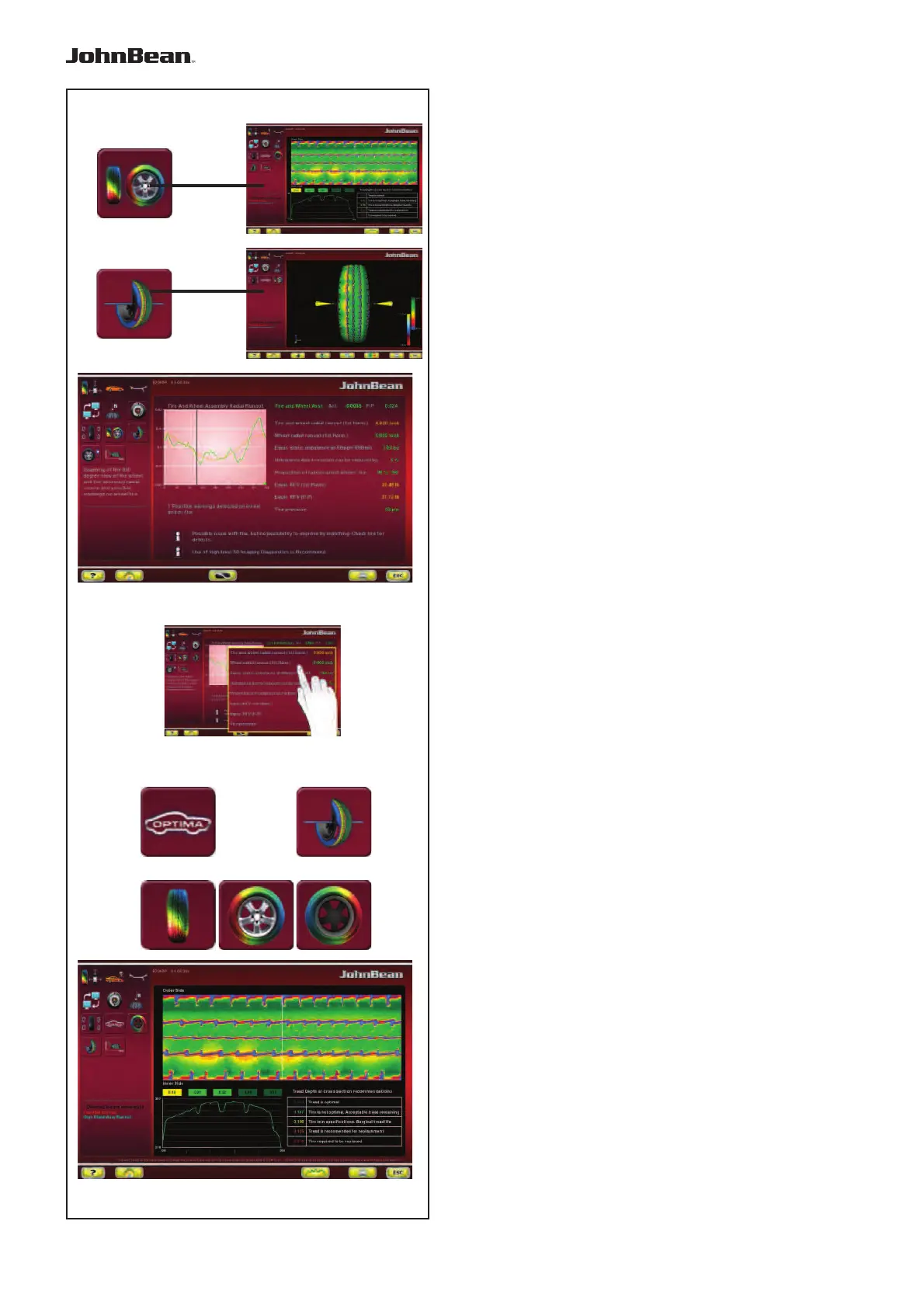
The Information Field in the “ASSEMBLY RUNOUT
INDICATION” screen (Fig. 6-72.a), contains the items
to access the “FULL DIAGNOSTIC” analysis screens:
1 Access the “TREAD PLOT” screen
2 Access the “3D PLOT” screen
Note:
Some areas of the screen can be enlarged (Fig.
6-72.b).
6.5.2 “TREAD PLOT” menu
The “TREAD PLOT” screen (Fig. 6-73) is
accessed with Item 1 in the “ASSEMBLY RUNOUT
INDICATION” screen (Fig. 6-72.a).
The screen presents a graphical and numerical
analysis of the wheel tread.
The screen contains the following Menu Items:
1
Go back to the “ASSEMBLY RUNOUT INDICATION”
screen.
2 “3D PLOT”, 3D view.
3 “TREAD PLOT”, tread analysis.
4 “INTERNAL SIDEWALL”, internal sidewall analysis.
5 “EXTERNAL SIDEWALL”, external sidewall analysis.
In the “TREAD PLOT” screen (Fig. 6-73) is used to
memorise the tread wear data of from one to four
wheels of a vehicle. Once the first wheel is entered the
“TREAD CONDITIONS REPORT” printout, containing
the information stored, is available.
..
_
..........