22
4-1
4-2
1 23 4
1 2
3
5
4
6
7
8
10
9
10
11
12
Layout
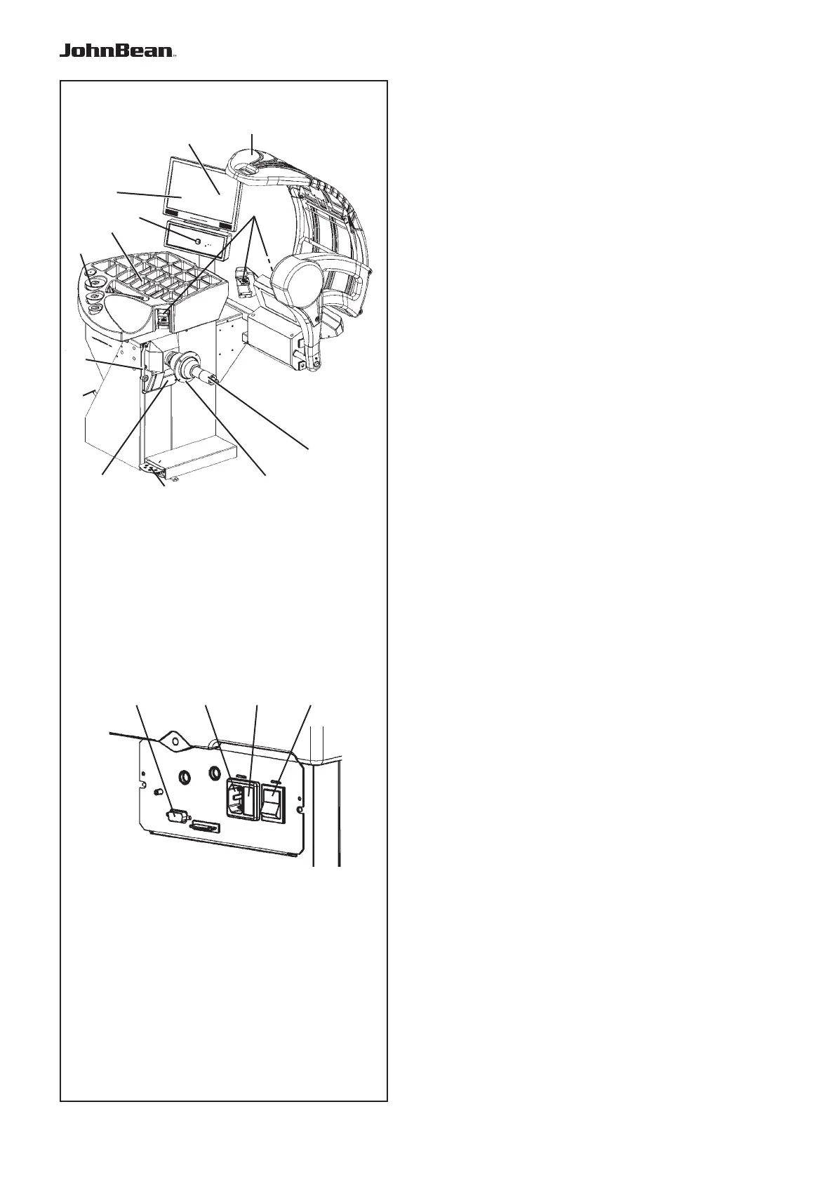
4.0 LAYOUT
Refer to Figure 4-1.
Nomenclature of the unit’s parts:
1. Display (F 4.1)
2. Input panel (F 4.1.2)
3. Internal gauge arm (F 4.8)
4. Flange
5. Stub shaft with hub nut
6. Weight compartments
7. Storage areas for cones and hub nuts
8. Wheel guard
9.
Brake Pedal and Power Clamp Operation (F 4.5)
10.
Camera (for data Acquisition)
11. Laser Pointer
12. Stop Button
Refer to Figure 4-2.
1. Mains switch (ON/OFF)
2. Fuse holder
3. Machine Power Supply
4. Video (VGA) Connector)
..
_
..........
1
2
3
5
4
7
8
9
10
11
5
12
7