168
7-03
B
7-05
7-06
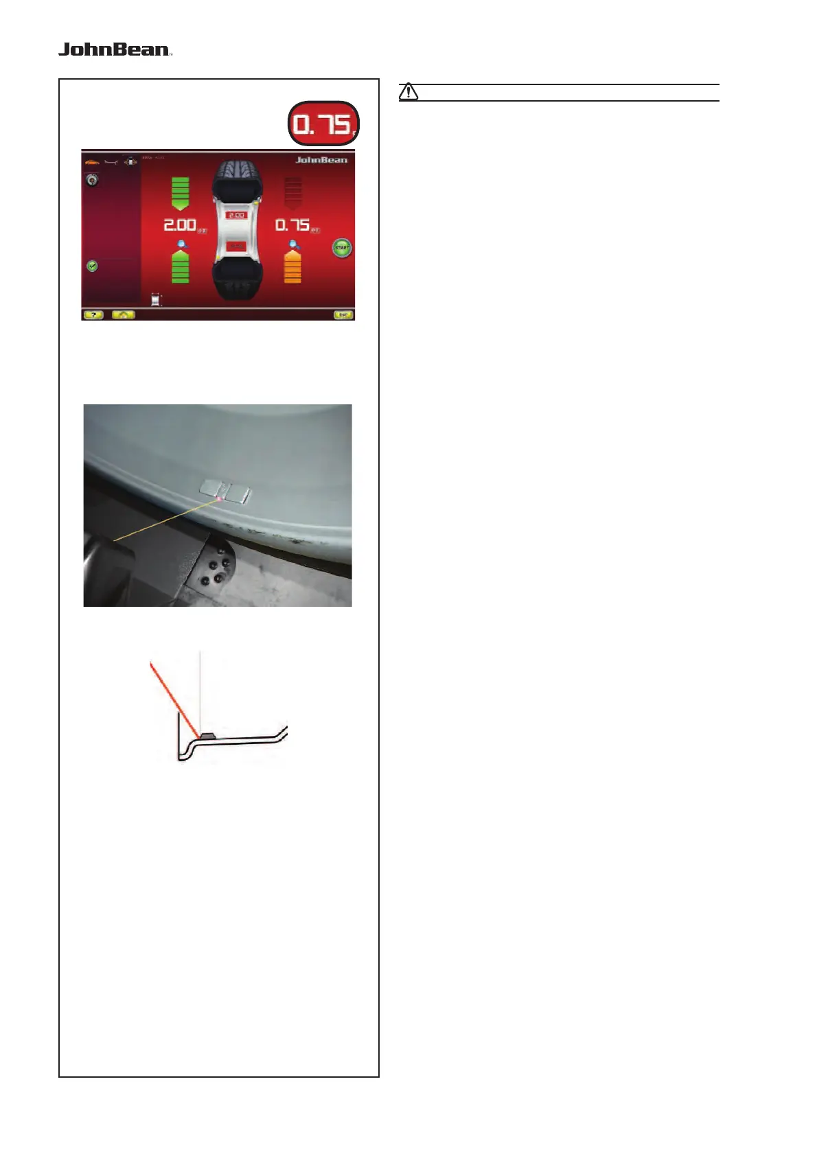
Operation
CAUTION: MOVE AWAY FROM THE WHEEL
• Press on the value (B, Fig. 7-03), to automatically
bring the wheel to the right-hand WAP position, apply
the adhesive weight on the end of the gauge arm
and fi x it in the suggested position (“1” + “beep”).
— At the end perform a Test Run.
7.0.1.1 Using the Laser Pointer
In Alu 2P and Alu 3P modes, with the Laser Pointer
m
ode ac
tive, the correction planes for adhesive
weights are precisely indicated by the laser pointer
directly on the rim (Fig. 7-05).
Note: When the indication is given by the laser
(if
enabled from service)
, the weight must not be
fi tted at 12 o’clock, but at the bottom of the
rim, precisely where indicated by the pointer.
Weights application at about 5 o’clock, on the right of
the laser point (Fig. 7-06).
There are at least two positions where the adhesive
weights can be fi tted, indicated by the Laser pointer,
depending on the wheel type and the balancing mode.
When a run is completed correctly the BALANCING
screen shows the correction values and the position
where the weights must be fi tted.
To make the corrections,
• Select an adhesive weight of the indicated size and
adjust it to the wheel radius by bending.
• If necessary, index the wheel precisely into the
correction position for the left plane. When the
correction position is reached, the two arrows on
the screen light up green.
• Press the pedal of the main shaft lock to hold the
wheel in this position.
• Clean the fitting position before attaching the
adhesive weights.
• Fit the balancing weight and firmly press the
adhesive weight onto the rim.
• Fit the second adhesive weight in the same manner.
The position for fi tting the weights indicated by the
Laser pointer can be varied for each correction
plane.
• See “RELOCATION” (F 6.3.3).
..
_
..........