246
i-1
Installation
i. Installation requirements
Space requirements
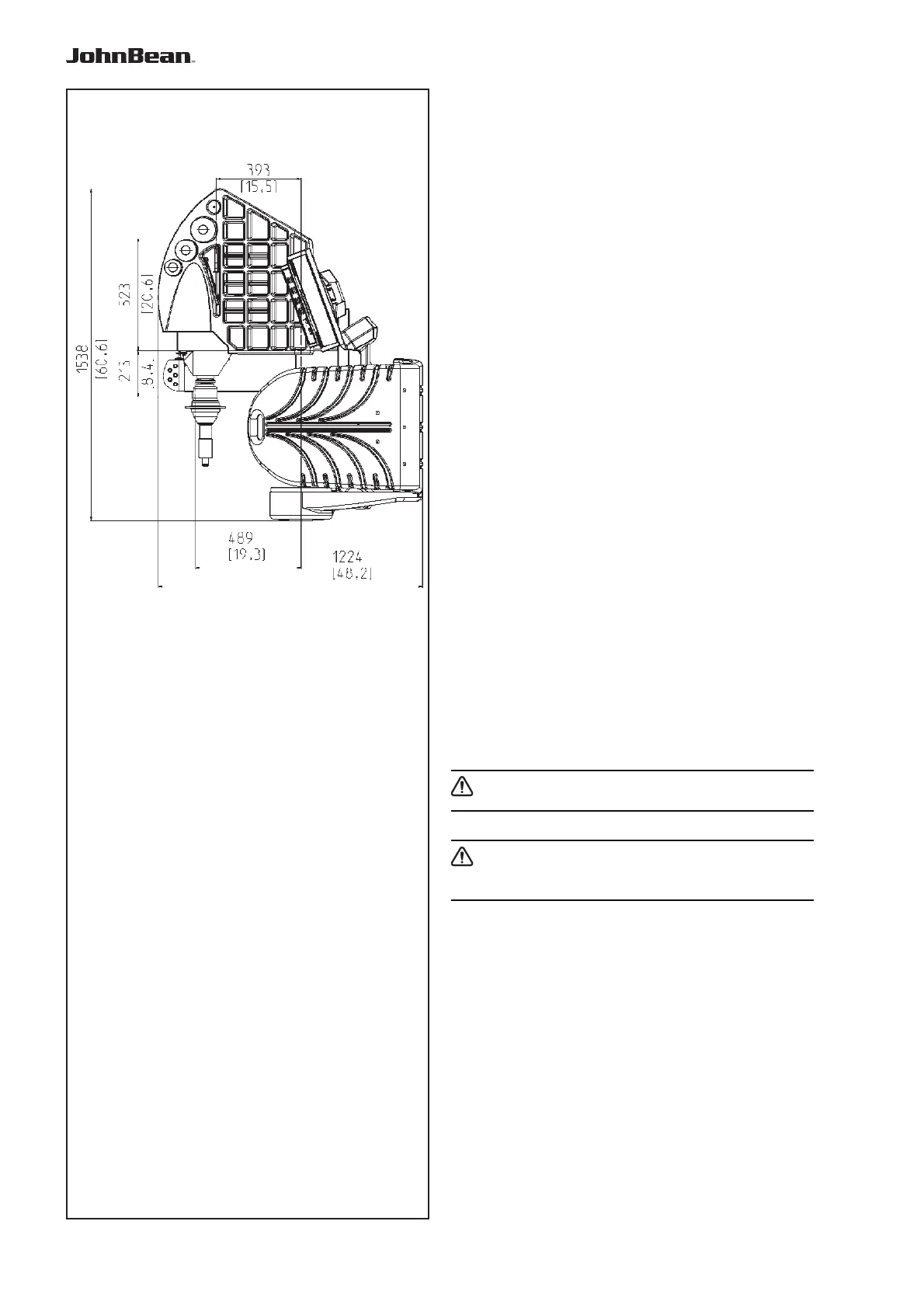
The drawi
ng show the minimum safety requirements:
The drawing has two sets of dimensions:
1 from the wall to the center of the holes: on
the left and top of the drawing
2 from the wall to the outline of the cabinet: on
the right and bottom of the drawing
Floor requirements
The fl oor should be:
- horizontal; +/- 1° tolerance
- even; within 2 mm
- able to bear the weight of the balancer as stated in
Chapter 2 of the Operator’s Manual.
The fl oor on which the balancer will be installed
should not relay vibrations from other devices or
from outside the building. External vibrations may
affect the accuracy of the unit.
Note:
The balancer must be positioned directly
on the fl oor. Do not use spacers to fi ll gaps.
If the above conditions are satisfi ed, the balancer
does not need fi xing to the fl oor.
Power supply requirements
Refer to Chapter 2 of the Operator’s Manual for mains
power requirements.
WARNING: ENSURE THAT AN APPROVED
WALL MAINS OUTLET IS AVAILABLE.
WARNING: NEVER GUIDE POWER SUPPLY
CABLES OVER THE FLOOR, UNLESS
PROTECTED BY AN APPROVED COVER.
..
_
..........
B 2000P