Network Control Module 300 Series Technical Bulletin 22
Wiring the Power Cord
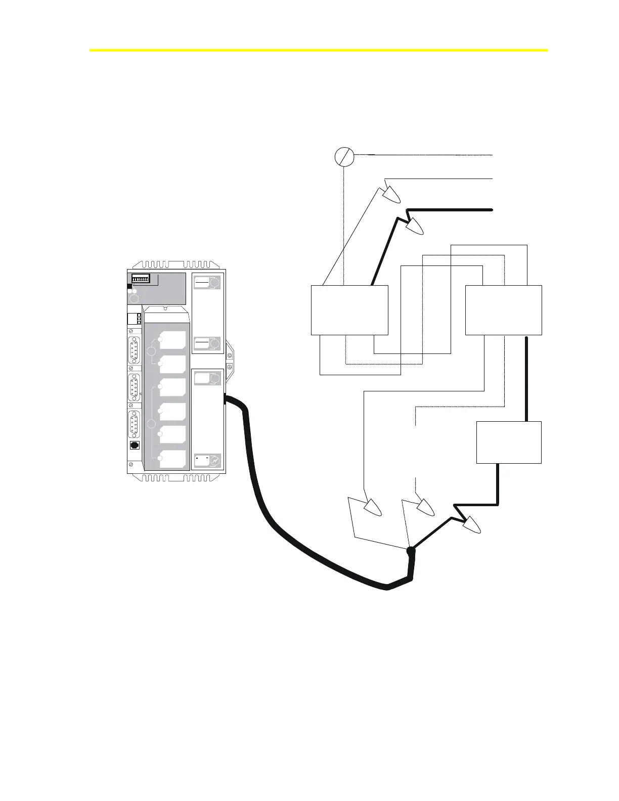
Figure 4 shows how to wire the NCM power cord into the power entry
box in the EWC22. Once this wiring is complete, the switch on the
power entry box controls power to the NCM.
1 2 3 4 5 6 7 8
1
2
3
4
5
6
7
8
I
N
O
U
T
R
E
L
O
A
D
7
8
P
O
W
E
R
O
N
C
O
N
F
I
G
.
E
N
D
O
FL
I
N
E
a
b
D
-
R
A
M
-ATTENTION -
PLEASE DIS CONNEDT BATTERY
BEFORE INSTALLING MEMORY
B
A
T
T
E
R
Y
NEXT SERVICE DATE:
R
E
F
N
2
-
N
2
+
a
b
I
S
A
S
L
O
T
S
I
I
I
I
V
C
O
M
M
-
P
O
R
T
S
I
I
I
P
O
W
E
R
S
U
P
P
L
Y
DISCO NNECT
POWER BEF ORE
SERVIC ING
DANGER
LI NE V OLTAG E
INSIDE
Ground (Green)
Safety
Ground
Input Power (White)
Input Power (Black)
ON/OFF
Switch
Black
Green
White
Auxiliary
Power
Outlet
Auxiliary
Power
Outlet
Use a UL Listed
crimp or splice
connection
to make the
ground bond.
Pwrcord
Figure 4: Wiring the Power Cord
For the Fire-Net NCM, refer to Figure 32 in Appendix A: Fire-Net
NCM.