Network Control Module 300 Series Technical Bulletin 95
NCM Battery Visual Inspection
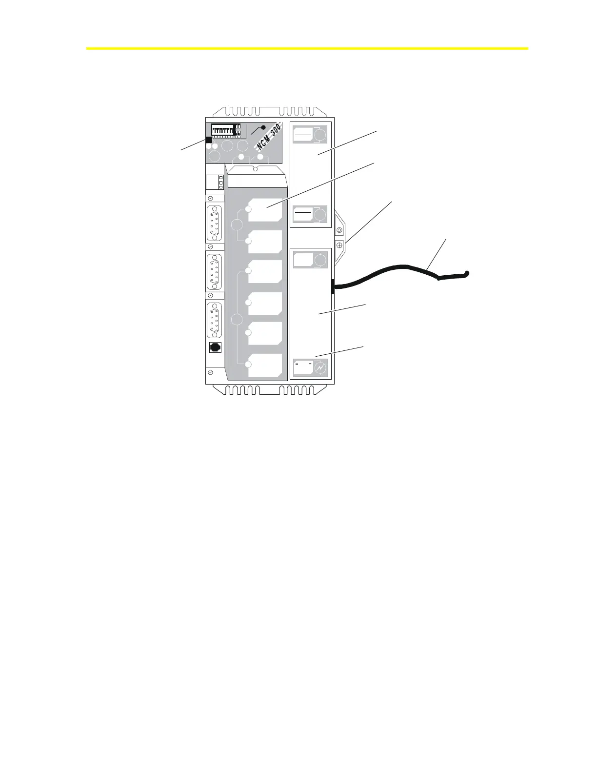
Refer to Figure 37 for battery and power supply location.
nc3power
Battery Cover
Power Supply Mounting Screw
Power Cord to Main AC
.
Power Supply
Power conditioning board is
under sheet metal at this end.
ISA Slot Cover
1 2 3 4 5 6 7 8
1
2
3
4
5
6
7
8
I
N
O
U
T
R
E
L
O
A
D
7
8
P
O
W
E
R
O
N
C
O
N
F
I
G
.
E
N
D
O
F
L
I
N
E
a
b
D
-
R
A
M
-ATTENTION -
PLEASE DISCONNEDT BATTERY
BEFORE INSTALLING MEMORY
B
A
T
T
E
R
Y
NEXT SERVICE DATE:
REF
N2
-
N2
+
a
b
I
S
A
S
L
O
T
S
I
I
I
I
V
C
O
M
M
-
P
O
R
T
S
I
I
I
P
O
W
E
R
S
U
P
P
L
Y
DISCONNECT
POWER BEFORE
SERVICING
DANGER
LINE V OLT AGE
INSIDE
Battery Fault
(LED)
Figure 37: NCM Battery and Power Supply
NCM Battery Status
When the battery status LED is off, the battery and battery charging
circuit are operating properly. You can check on the battery status in
three ways:
• Light-Emitting Diode (LED) indicator
• NCM Diagnostics (“NCM Misc Data”) from Network map
• NCSETUP for Windows or, NCSETUP (DOS version, choose the
Read NC Type option [good, bad, not installed])
Notes: The LED may light for several seconds when a discharged
battery has been installed. If this condition persists for more than
one minute, replace the battery.
The Battery Fault LED indicates whether a battery is installed. It does
not indicate the charge level or operational status of the battery.

 Loading...