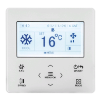
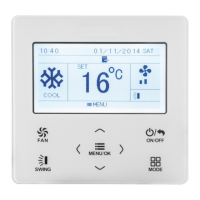
Wired Controller DWCR2
37
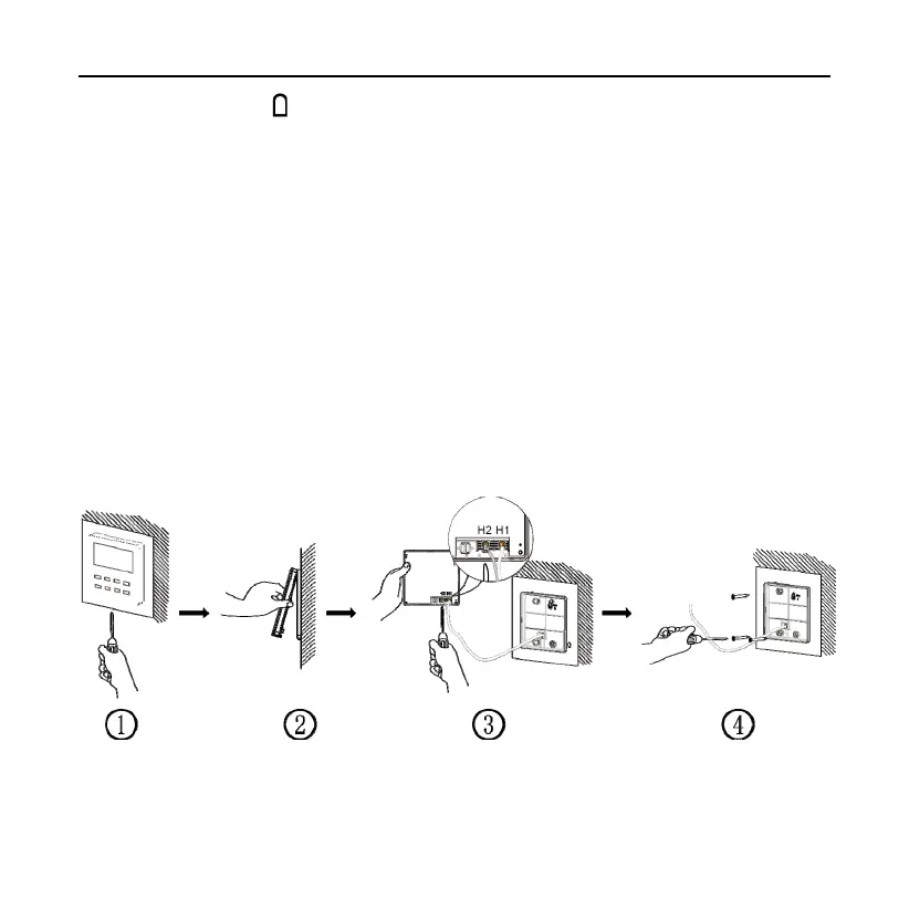
this wire through the “ ” hole at the bottom side of the base of the wired controller;
(3). Screw the base of the wired controller onto the wall and then use screw
M4×25 to attach the base and back plate on the wall together.
(4). Connect two-conductor twisted pair wire to H1 and H2 terminals and then
tighten the screws (observe polarity);
(5). Block the 18AWG two-conductor wire into the groove on the left side of
the wiring column. Bundle the front panel of wired controller to its base.
Note:
If the procedures in point 2 and point 5 mentioned above are hard
to
do
because
the diameter of the selected communication wire is
too
thick,
peel off the sheathed layer to the appropriate length
.
4.4 Disassembly
Fig. 24 Disassembly diagram for wired controller