Communications bus and supply power
wiring guidelines
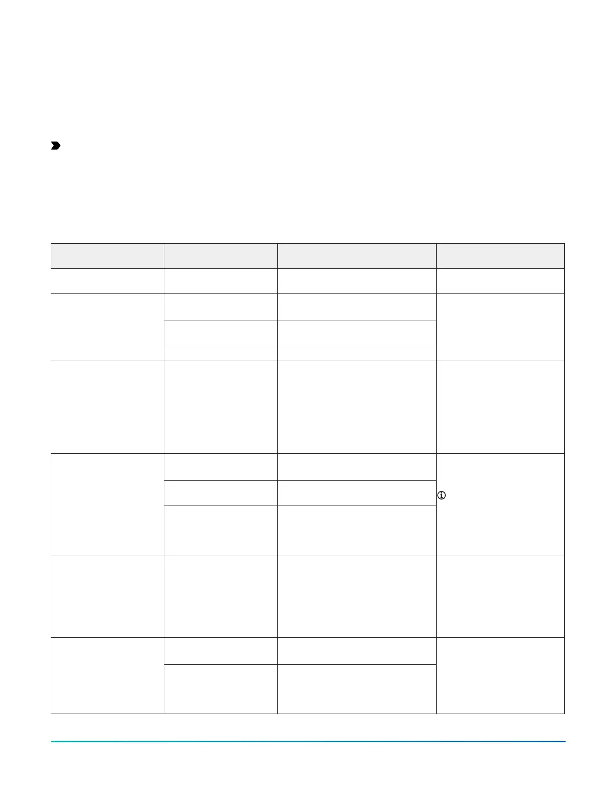
Table 5 provides information about the functions, ratings,
and requirements for the communication bus and supply
power terminals. The table also provides guidelines for
wire sizes, cable types, and cable lengths for wiring the
controller's communication buses and supply power.
Important: Refer to the N2 Modernization Guide for
Legacy N2 Controllers (LIT-12012045) for guidelines
when you use this device on an N2 bus.
In addition to the guidelines in Table 5, observe the
following guidelines when wiring an FC Bus, SA bus or the
24 VAC supply power:
• Run all low-voltage wiring and cables separate from
high-voltage wiring.
• All FC and SA bus cables, regardless of wire size, should
be twisted, insulated, stranded copper wire.
• Shielded cable is strongly recommended for all FC and
SA bus cables.
• Refer to the FX-PC Series Controllers MS/TP
Communications Bus Technical Bulletin (LIT-12011670)
for detailed information regarding wire size and cable
length requirements for FC and SA buses.
Communications bus and supply power terminal blocks, ratings, and requirements
Table 5: Communications bus and supply power terminal blocks, functions, ratings, requirements, and cable
guidelines
Terminal block/Port label Terminal labels Function, electrical ratings/
Requirements
Recommended cable type
Ethernet (Ports) (CGE
models)
ETH-1 and ETH-2 Connect to BACnet/SC or BACnet/IP
Network
Ethernet ports; 10/100 Mbps; 8-
pin RJ-45 connector
+
-
FC Bus Communications
COM Signal Reference (Common) for Bus
communications
FC BUS (CGM models)
SHD Isolated terminal
0.6 mm (22 AWG) stranded, 3-
wire twisted, shielded cable
recommended
FC BUS (Port) (CGM models) FC Bus RJ-12 6-Position Modular Connector
provides:
• FC Bus Communications
• FC Bus Signal Reference and 15
VDC Common
• 15 VDC, 180 mA, Power for MAP
Gateway or ZFR (or ZFR Pro)
Wireless Router
24 AWG 3-pair CAT 3 Cable <30.5
m (100 ft)
+
-
SA Bus Communications
COM SA Bus Signal Reference and 15 VDC
Common
SA BUS
POWER 15 VDC Supply Power for Devices on the
SA Bus
(Maximum total current draw for SA Bus
is 240 mA.)
0.6 mm (22 AWG) stranded, 4-
wire (2 twisted-pairs), shielded
cable recommended.
Note: The + and - wire
are one twisted pair, and
the COM and POWER are
the second twisted pair of
wires.
SA BUS (Port) SA BUS (CGM)
Sensor (CGE)
RJ-12 6-Position Modular Connector
provides:
• SA Bus Communications
• SA Bus Signal Reference and 15
VDC Common
• 15 VDC Power for devices on the SA
Bus
24 AWG 3-pair CAT3 cable <30.5
m (100 ft)
HOT 24 VAC Power Supply - Hot
Supplies 20–30 VAC (Nominal 24 VAC)
24V~
COM 24 VAC Power Supply Common
(Isolated from all other Common
terminals on controller)
14 VA
0.8 mm to 1.0 mm
(18 AWG) 2-wire
< 30 m (100 ft)
F4-CG Series General Purpose Application Controllers Installation Guide 11