Setup and adjustments
Important: Electrostatic discharge can damage
controller components. Use proper electrostatic
discharge precautions during installation, setup, and
servicing to avoid damaging the controller.
Configuring N2 communications (CGM
models only)
About this task:
N2-capable controllers support the full range of possible
N2 device addresses provided by the N2 protocol standard
(1-254).
To configure a CGM controller to communicate using the
N2 protocol, complete the following steps:
1. Disconnect the 24 VAC supply from the controller.
2. Set the address switches to the desired N2 address.
For details about setting a device address, see
Setting the device address on CGM models.
3. Reconnect the 24 VAC supply to the controller.
4. Using an SA Bus connection, download the
firmware and controller application file configured
for N2 to the controller.
Switching the Communications Protocol
from N2 to MS/TP
About this task:
For N2 sites that are converting to BACnet MS/TP, you can
switch the communications protocol of N2-configured
controllers back to BACnet MS/TP.
To switch the CGM controller operating in N2 mode back
into BACnet MS/TP mode, complete the following steps:
1. Disconnect the 24 VAC supply from the controller.
2. Set the address switches to the desired BACnet
MS/TP address. For details about setting a device
address, see Setting the device address on CGM
models.
3. Reconnect the 24 VAC supply to the controller.
4. Using an SA Bus connection, download a controller
application file configured for BACnet MS/TP to the
controller.
Configuring wireless communications
(CGM models only)
To configure a CGM controller for use with the ZFR Pro
Series Wireless Field Bus system, complete the following
steps:
1. Disconnect the 24 VAC supply from the controller.
2. Wire the input/output terminals and SA Bus.
Note: In wireless network applications, do
not connect any wires to the FC Bus terminal
block. (Connect the SA/FC terminal block on
expansion modules to an SA Bus only.)
3. Important: Before the CGM controller is powered
on, connect the FX-ZFR Pro Wireless Field Bus
Router to the FC Bus port (RJ-12 modular jack) on
the front of the controller.
4. Ensure that the controller's rotary switches are
set to the correct device address. For details about
setting a device address, see Setting the device
address on CGM models.
5. Reconnect the 24 VAC supply to the controller.
For more information about the ZFR Pro Wireless
Field Bus system, refer to the WRG1830/ZFR183x Pro
Series Wireless Field Bus for Facility Explorer Systems
Technical Bulletin (LIT-12013796).
Setting the device address on CGM
models
The CGM controllers are manager devices on MS/TP (FC
or SA) Buses. Before you operate controllers on a bus,
you must set a valid and unique device address for each
controller on the bus.
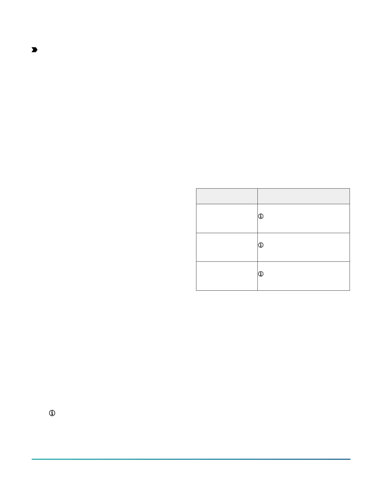
The following table describes the valid rotary switch
device addresses for communications bus applications:
FC Bus communication
mode
Valid device address range
Wired MS/TP
communication
4-127
Note: Addresses 0-3 are
reserved and not for use on
equipment controllers.
ZFR Pro Wireless
communication
4-127
Note: Addresses 0-3 are
reserved and not for use on
equipment controllers.
N2 communication 1-254
Note: Addresses 0 and 255 are
reserved and not for use on
equipment controllers.
The device address is a decimal address set using three
rotary switches located at the top of the controller. The
numbers are ordered from left to right, 100s, 10s, and 1s.
As shown in the following figure, the switches are set to 1
2 3, designating this controller's device address as 123.
F4-CG Series General Purpose Application Controllers Installation Guide18