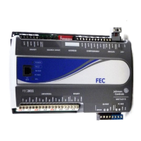
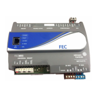
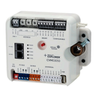
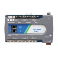
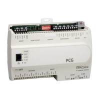
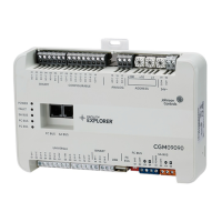
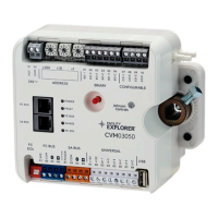
Table 11: FEC26 Technical Specifications
RS-485, field selectable between BACnet MS/TP and N2 communications:
3-wire FC Bus between supervisory controller and field controllers.
4-wire SA Bus between field controller, network sensors, and other sensor/actuator
devices, includes a lead to source 15 VDC supply power (from field controller) to
bus devices.
N2 Open Protocol:
N2/FC Bus: 1.0mm (18 AWG) standard 3-wire, twisted, shielded cable recommended
between the supervisory controller and field controllers
Communications Bus
FEC26 Series: H8SX/166xR Renesas® 32-bit microcontroller
Processor
640 KB flash memory and 128 KB RAM
Memory
FEC26 Series:
6 - Universal Inputs: Defined as 0–10 VDC, 4-20 mA, 0–600k ohm, or Binary Dry
Contact
2 - Binary Inputs: Defined as Dry Contact Maintained or Pulse Counter/Accumulator
Mode
3 - Binary Outputs: Defined as 24 VAC Triac (selectable internal or external source
power)
4 - Configurable Outputs: Defined as 0–10 VDC or 24 VAC/DC Field-Effect
Transistor (FET) BO
2 - Analog Outputs: Defined as 0–10 VDC or 4–20 mA
Input and Output Capabilities
Input: 16-bit resolution
Output: 16-bit resolution, +/- 200 mV accuracy in 0-10 VDC applications
Analog Input/Analog Output Resolution
and Accuracy
Input/Output: Fixed Screw Terminal Blocks
SA/FC Bus and Supply Power: 4-Wire and 3-Wire Pluggable Screw Terminal
Blocks
SA/FC Bus Port: RJ-12 6-Pin Modular Jacks
Terminations
Horizontal on single 35 mm DIN rail mount (preferred), or screw mount on flat surface
with three integral mounting clips on controller
Mounting
Enclosure material: ABS and polycarbonate, Rating V0 minimum
Protection Class: IP20 (IEC529)
Housing
FEC26 Series: 150 x 190 x 53 mm (5-7/8 x 7-1/2 x 2-1/8 in.) including terminals and
mounting clips
Note: Mounting space requires an additional 50 mm (2 in.) space on top, bottom
and front face of controller for easy cover removal, ventilation and wire
terminations.
Dimensions(Height x Width x Depth)
0.5 kg (1.1 lb)Weight
26FEC26 Field Equipment Controllers Installation Instructions

 Loading...

