FIRECLASS Fire detection system Make Jumper and DIP Switch Settings
Installation Guide Doc. version 2.0 27
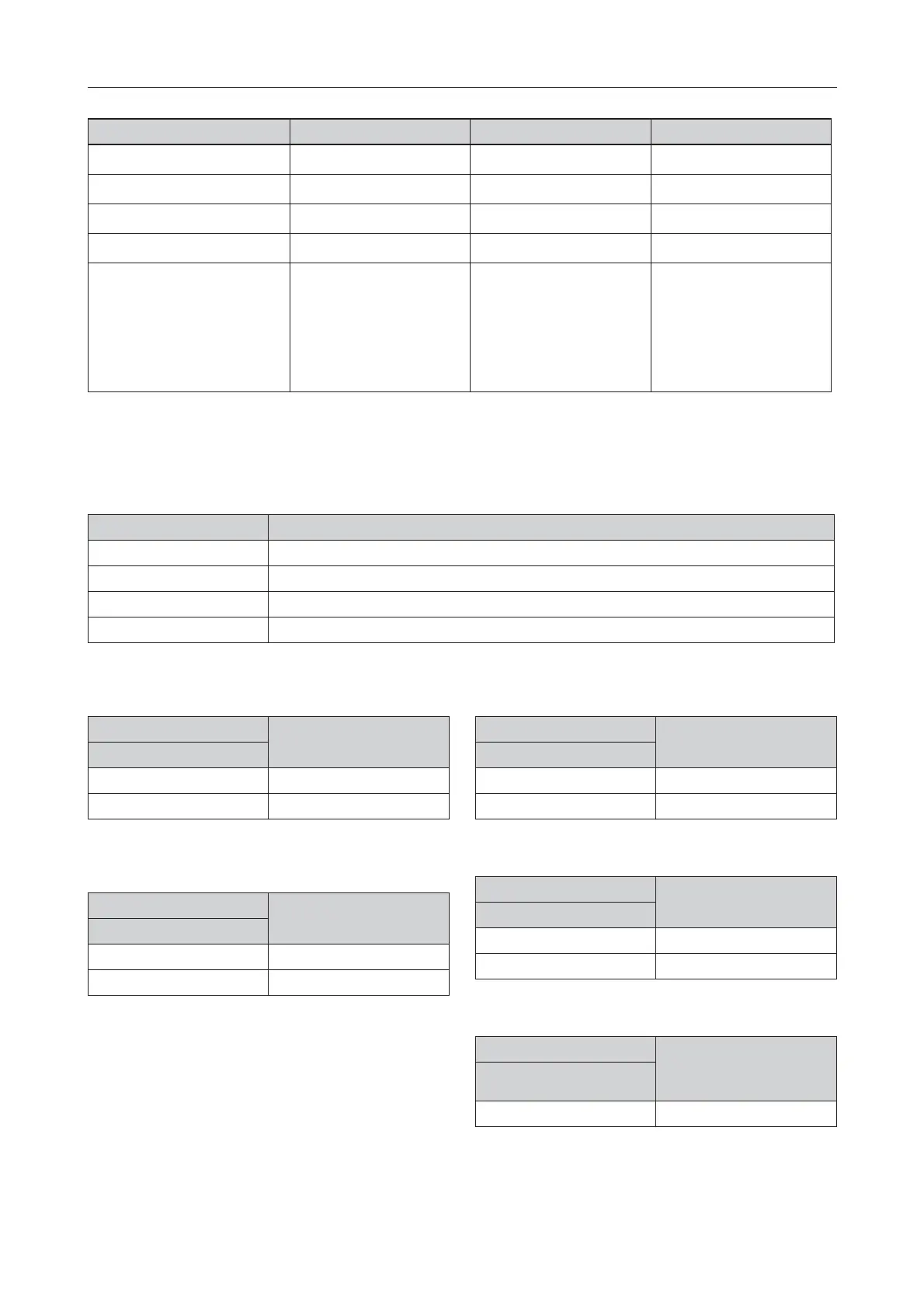
Jumper 1-2 2-3 OPEN
J1 – Relay 3
Normally Closed
[1]
Normally Open N/A
J2 – Relay 4
Normally Closed
[1]
Normally Open N/A
J3 – MCPU Watchdog
Enabled
[1]
Active (MCPU in reset) Enabled
J4 – LIOMCU Watchdog
Enabled
[4]
Active (LIOMCU in reset) Disabled
J5 – MCPU Boot Mode
[2]
H1 Header
H2 Header
H3 Header
LIOMCU Boot Mode
[3]
Enabled
Enabled
Enabled
Enabled
Enabled
-
-
-
-
-
Disabled
[1]
Disabled
[1]
Disabled
[1]
Disabled
[1]
Disabled
[1]
Table 5: FC-FI - Jumper settings
[1] Default.
[2] For updating the MCPU Boot Loader. The mode is entered after an MCPU reset.
[3] For updating the LIOMCU firmware. The mode is entered after a LIOMCU rest. The LIOMCU Watchdog has to be disabled
during update of firmware.
[4] Default. Disable this before a firmware update.
Header Function
H1, H2, H3 not fitted Standard operational mode or Configuration Download mode.
H1 fitted -
H2 fitted Clear the stored data when the panel is restarted.
H3 fitted Panel configuration download from USB memory stick mode.
Table 6: FC-FI - Header H1, H2, H3 Functions
SW6 Sounders activated by
External Alarm
Position 7
[1]
OFF * Disabled
ON Enabled
Table 7: Sounders activated by Emergency Alarm setting
* Default
[1] The number 7 is located on the switch, not on the PCB.
SW6 Earth Fault Monitoring
Position 8
[1]
OFF Disabled
ON * Enabled
Table 8: FC-FI - Earth Fault Monitoring setting
* Default
[1] The number 8 is located on the switch, not on the PCB.
SW7 RL3 activated by
ALARM
Position 1
OFF * Disabled
ON Enabled
Table 9: FC-FI - RL3 relay activated by ALARM setting
* Default.
SW7 RL3 activated by FAULT
Position 2
OFF * Disabled
ON Enabled
Table 10: FC-FI - RL3 relay activated by FAULT setting
* Default.
SW7 RL4 activated by
ALARM
Position 3
OFF * Disabled
Table 11: FC-FI - RL4 relay activated by ALARM setting
* Default
 Loading...