FIRECLASS Fire detection system FB800 Fused 24V Outputs Board Details
Installation Guide Doc. version 2.0 39
14.4 FB800 Fused 24V Outputs Board
Details
14.4.1 Mount the Units in the Slot Card
Cage
1 Assemble the layers of units with the mounting
bracket, as shown in Fig. 31. Use the layer positions
you determined in the section “Decide on a Layer
Order”. Use the provided stand-off pillars.
2 Fix the assembly into the slot card cage as shown in
Fig. 31.
3 Connect the IOB ribbon cable to the connector on
the FC-FI main board marked ‘XP3 IOBUS’ – this is
on the right hand of the FC-FI board, about one third
down from the top.
4 Connect the ribbon cable from the FC-FI to the left-
hand IOB800 unit. On the unit connect to the con-
nector marked ‘XP1’ on the PCB.
5 If applicable, chain on the IOB to further units. Chain
from ‘XP1’ on the left hand unit to ‘XP2’ on the next
one to the right. Route the IOB ribbon cable above
the upper edge of the mounting bracket.
6 For an FB800 fuse board, connect the earths and
power etc.
7 Connect the ribbon cable from the FC-FI to the left-
hand IOB800 unit. On the unit connect to the con-
nector marked ‘XP1’ on the PCB.
If applicable, chain on the IOB to further units. Chain
from ‘XP1’ on the left hand unit to ‘XP2’ on the next one
to the right. Route the IOB ribbon cable above the upper
edge of the mounting bracket.
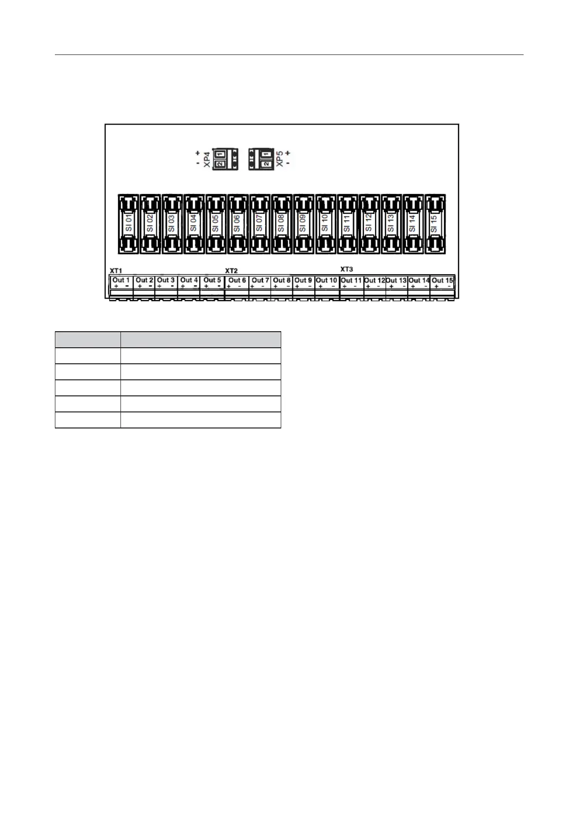
Fig. 30: FB800 Terminal Positions
Connector Function
XT1 Power 24V fused Outputs 1 to 5
XT2 Power 24V fused Outputs 6 to 10
XT3 Power 24V fused Outputs 11 to 15
XP4 Power 24V Input
XP5 Power 24V Output
Table 36: FB800 Terminal Functions
 Loading...