RWF II ROTARY SCREW COMPRESSOR UNITS
OPERATION
070.610-IOM (JUN 11)
Page 15
DEMAND PUMP OIL SYSTEM
This system is designed to provide adequate compressor
lubrication when there is low differential oil pressure across
the compressor suction and discharge for some high stage
applications and booster applications as required.
On startup, Quantum™LX will calculate the pressure dif
ferential between the compressor discharge and the main oil
injection port. If this differential is less than 35 psi, then the
demand pump will turn on and will continue to run until 45 psi
differential is obtained. Then, the pump will shut down and
start only when the differential pressure falls below 35 psi.
NOTE: For alarm descriptions and shutdown or cutout
parameters, see publication 090-020 O.
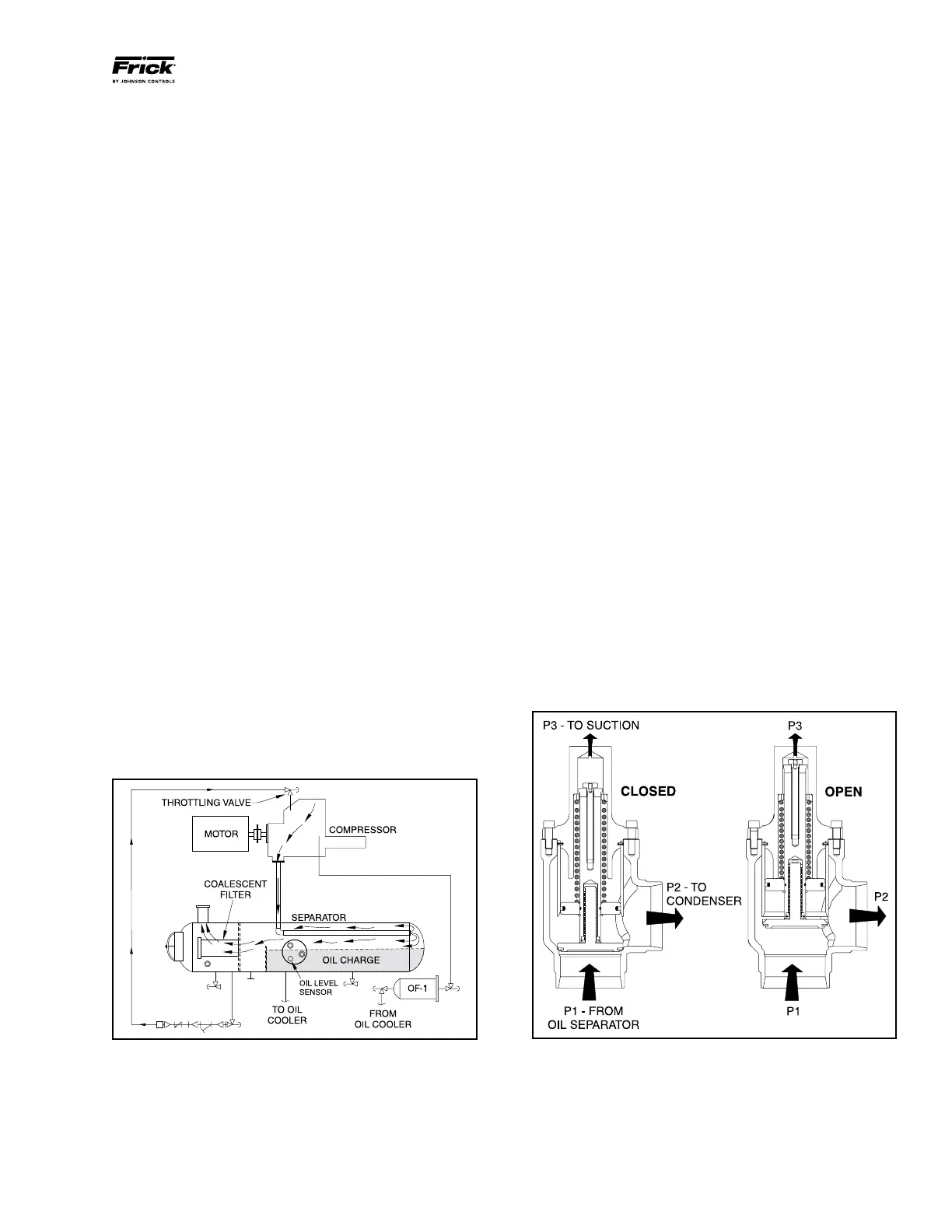
COMPRESSOR OIL SEPARATION SYSTEM
The RWF II is an oil ooded screw compressor. Most of the
oil discharged by the compressor separates from the gas ow
in the oil charge reservoir. Some oil, however, is discharged
as a mist which does not separate readily from the gas ow
and is carried past the oil charge reser voir. One or more
coalescer lter elements then COALESCE the oil mist into
droplets which fall to the bottom of the coalescer section of
the oil separator. See Figure 16. The return of this oil to the
compressor is controlled by a throttling valve on both high
stage and booster applications.
NOTE: Open throttling valve only enough to keep coalescer
end of separator free of oil.
The sight glass located near the bottom of the coales cer sec-
tion of the oil separator should remain empty during normal
operation. If an oil level develops and remains in the sight
glass, a problem in the oil return separation system or com-
pressor operation has developed. Refer to MAINTENANCE
for information on how to correct the prob lem.
NOTE: The normal operating level is midway between the
two sight glasses located midway along the oil separa-
tor shell.
Figure 16 - Oil Separation System
COLD-START SYSTEM
The RWF II package is equipped with a special "coldstart"
discharge check valve (Figure 17) on the gas outlet connec
tion of the oil separator. This valve causes the oil separator
to develop oil pressure rapidly on initial start in order to
lubricate the compressor without requiring an oil pump, even
in cold ambient temperatures with all pressures equalized.
For high-stage packages, the coldstart valve is equipped
with a large spring that creates 30 psi of pressure in the oil
separator (above suction pressure), for lubrication of the
compressor.
Once the compressor is running it will begin to force gas to
the condenser at connection P2. As the condenser heats up it
will begin to rise in pressure as the compressor suction pulls
down in pressure. As soon as differential pressure is devel
oped between the condenser and suction, these pressures
act across a piston inside the coldstart valve to partially
overcome the spring force. When the differential pressure
reaches and exceeds 30 psi, the piston fully overcomes the
spring force and powers the valve fully open for very low
operating pressure drop.
For booster applications, the valve is equipped with a lighter
spring which produces 7 psi oil pressure above suction pres
sure before it fully powers open. An oil pump is required to
ensure compressor lubrication.
The RWF II package is also equipped with a suction check
valve bypass. The oil separator will slowly bleed down to ap
proximate system suction pressure when the unit is stopped.
This allows the compressor drive motor to have an easier
start, and the discharge check valve will seat more tightly. See
the "SUCTION CHECK VALVE BYPASS" section for operation.
NOTE: For alarm descriptions and shutdown or cutout
parameters, see publication 090-020 O.
Figure 17 - Cold-Start Valve
 Loading...


