RWF II ROTARY SCREW COMPRESSOR UNITS
OPERATION
070.610-IOM (JUN 11)
Page 16
COMPRESSOR HYDRAULIC SYSTEM
The compressor hydraulic system moves the movable slide
valve (MSV) to load and unload the compressor. It also moves
the movable slide stop (MSS) to increase or decrease the
compressor’s volume ratio (Vi).
The hydraulic cylinder located at the inlet end of the SGC
compressor serves a dual purpose. It is separated by a xed
bulkhead into two sections. The movable slide valve (MSV)
sec tion is to the left of the bulkhead and the movable slide
stop (MSS) to the right. Both sections are considered double
acting hydraulic cylinders as oil pressure moves the pistons
in either direction.
Both sections are controlled by doubleacting, fourway
solenoid valves which are actuated when a signal from the
appropriate micropro cessor output energizes the solenoid
valve. Valves V1, V2, SC1, SC3, and SC4 are always open.
NOTE: The solenoid coils can be serviced or replaced
without evacuating the package. However, if the hy-
draulic solenoid valves or manifold block needs to be
serviced or replaced, then the compressor package must
be evacuated.
SINGLE-ACTING MODE - High Stage
Close valve at SC2
Open valve at BP (bypass)
High stage compressor loading: The compressor loads when
MSV solenoid YY2 is energized and oil ows from the unload
side of the cylinder out port SC1, through valve ports A and
T to compressor suction. Simultaneously, discharge pressure
loads the slide valve.
High stage compressor unloading: The compressor unloads
when MSV solenoid YY1 is energized and oil ows from the
oil manifold through valve ports P and A to cylinder port SC1
and enters the unload side of the cylinder. Simultaneously,
gas on the load side of the cylinder is vented through port
SC2 and valve BP to compressor suction.
NOTE: To control the rate of loading and unloading, change
cycle time, proportional band, and dead band setpoints
with Quantum control. If additional control is needed,
throttle SC2 or BP.
DOUBLE-ACTING MODE - Booster
Open valve at SC2
Close valve at BP (bypass)
Booster Compressor Loading: The compressor loads when
MSV solenoid YY2 is energized and oil ows from the oil
manifold through valve ports P and B to cylinder port SC2
and enters the load side of the cylinder. Simultaneously, oil
con tained in the unload side of the cylinder ows out cylinder
port SC1 through valve ports A and T to com pressor suction.
Booster Compressor Unloading: The compressor un loads
when MSV solenoid YY1 is energized and oil ows from the
oil manifold through valve ports P and A to cylinder port SC1
and enters the unload side of the cylinder. Simultaneous ly,
oil contained in the load side of the cylinder ows out of
compressor port SC2 through valve ports B and T to com
pressor suction.
NOTE: To control the rate of loading and unloading, change
cycle time, proportional band, and dead band setpoints
with Quantum control. If additional control is needed,
throttle SC2 or BP.
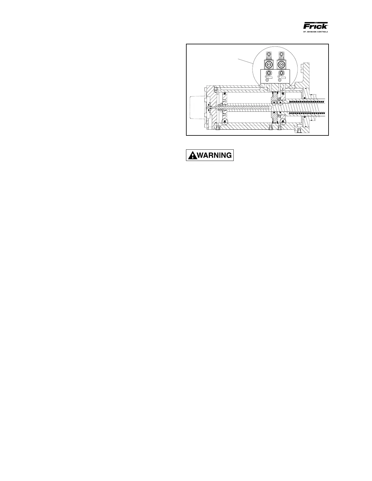
SC1
SC3
SEE HYDRAULIC
SCHEMATIC
FOR FUNCTIONAL
VIEW OF VALVE
OPERATION
Figure 18
NEVER open valve BP and valve SC2
at the same time during compressor
operation.
VOLUME RATIO CONTROL
NOTE: See Figure 19 for port references.
Open valve at SC3
Open valve at SC4 (not used on models 496,676,856,1080)
Compressor Vi increase: The volume ratio Vi is increased
when MSS solenoid valve YY3 is energized and oil ows from
the oil manifold through valve ports P and A to compressor
port SC3, enters the increase side of the cylinder and over
comes the decrease spring tension. Simultaneously, oil ows
from SC4 port through valve ports B and T to compressor
suction. On models 496, 676, 856, and 1080 the SC4 port
does not exist. The inboard side of the slide stop piston is
at suction pressure.
Compressor Vi decrease: The volume ratio Vi is decreased
when MSS solenoid valve YY4 is energized and oil ows from
the oil manifold through valve ports P and B to compressor
port SC4, enters the decrease side of the cylinder. Simultane
ously, oil ows form SC3 port through valve ports A and T to
compressor suction. On models 496, 676, 856, and 1080 the
SC4 port does not exist. On these models, YY4 is energized
which permits oil to vent from port A to T with assistance
from the unloader spring.
TO CONTROL THE RATE OF VI CHANGE, THROTTLE THE
NEEDLE VALVE AT SC3 PORT.
COMPRESSOR OIL COOLING SYSTEMS
The RWF II unit can be equipped with one of several sys
tems for controlling the compressor oil tempera ture. They
are single or dualport liquid injection and thermo syphon
or watercooled oil coolers. Each system is autom ati cally
controlled, independent of compressor loading or unloading.
Oil cooling systems should maintain oil temperature within
the following ranges for R717:
Liquid Injection External*
Oil Cooling Oil Cooling
130 170°F 120 160°F
* Thermosyphon oil cooling (TSOC) or Water cooled oil
cooling (WCOC).
 Loading...


