RWF II ROTARY SCREW COMPRESSOR UNITS
MAINTENANCE
070.610-IOM (JUN 11)
Page 36
VOLUME RATIO CONTROL TRANSMITTER -
SLIDE STOP
TROUBLESHOOTING
Conrm the setup of channel 15 on the calibration or analog
board #1 setup screen.
Troubleshoot the slide stop linear transmitter on channel 15
of the P7B terminal strip of the analog board in the same
manner as the slide valve transmitter.
REPLACEMENT
The Volume Ratio Control Transmitter is located on the right
side of the compressor (facing the shaft) at the inlet end.
See Figure 39.
The linear transmitter with hermetic enclosure is based on
the inductive measuring principle. It features removable
electronics (from the sensor well) eliminating the need to
evacuate the compressor for replacement. This type of
transmitter is dedicated to volume ratio control and has no
user adjustments.
1. Shut off control power.
2. Remove DIN connector plug from transmitter.
3. Loosen set screws.
4. Remove transmitter unit.
5. Install new transmitter unit.
6. Tighten set screws.
7. Apply DIN connector plug to transmitter.
8. Turn on control power.
NOTE: For calibration of the volume ratio control unit,
refer to the Calibration Instructions in publication 090-
021 O for operators or 090-022 O for service technicians.
Figure 39 - Volume Ratio Control Transmitter
TEMPERATURE SENSOR
TROUBLESHOOTING
Conrm the setup of the channel on the calibration or analog
board #1 setup screen. Is the temperature probe reading bot
tom end 459°F or top end +463°F? If reading bottom end,
the probe or wire(s) to the probe are open or the probe is
shorted to ground pulling down the power/excitation. Check
the power at the analog board between the + and – of the
channel for that probe. In Example, discharge temperature
would be Channel 2 on the P4A terminal strip of the analog
board. Is there a signal of 12 – 15 vdc? If yes, the probe is
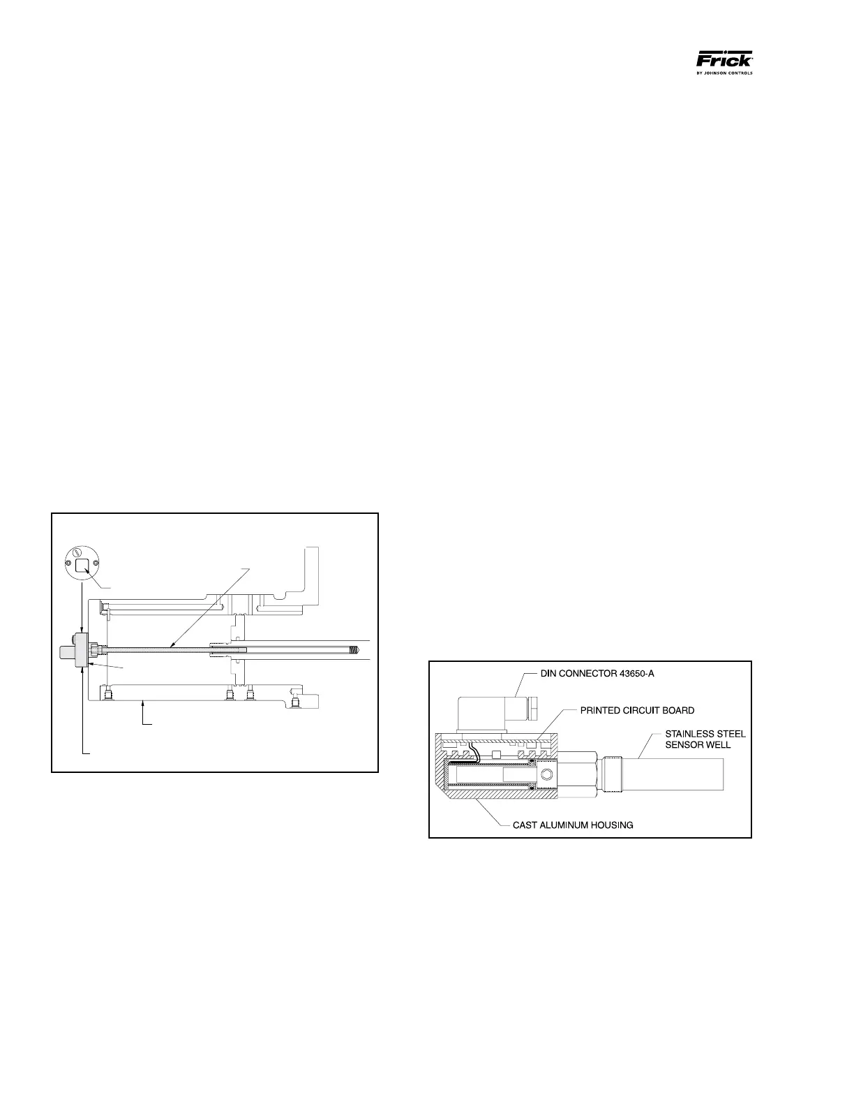
CAPACITY LINEAR TRANSMITTER -
SLIDE VALVE
REPLACEMENT
The Capacity Linear Transmitter is located on the end of the
compressor unload cylinder, see Figure 38.
The linear transmitter with hermetic enclosure is based on
the inductive measuring principle. It features removable
electronics (from the sensor well) eliminating the need to
evacuate the compressor for replacement. This type of trans
mitter is dedicated to capacity control and is not adjustable.
1. Shut off control power.
2. Remove DIN connector plug from transmitter.
3. Loosen cap screws.
4. Remove transmitter unit.
5. Install new transmitter unit.
6. Tighten cap screws.
7. Apply DIN connector plug to transmitter.
8. Turn on control power.
NOTE: For calibration instructions, refer to Quantum
™
LX
Operator's Manual, 090-020 O.
END VIEW
DIN CONNECTOR
STAINLESS STEEL WELL
HEAT ISOLATOR
CAST ALUMINUM HOUSING
COMPRESSOR UNLOAD CYLINDER
SHADED AREA SHOWS
CAPACITY LINEAR TRANSMITTER
Figure 38 - Capacity Linear Transmitter
TROUBLESHOOTING THE SENSOR
Ensure that the channel is properly congured on the Cali
bration or Analog board setup screen for the type sensor
being used.
Check that supply voltage to the sensor is 12 15 VDC on
red and black wire for Channel 14, P7A terminal strip of the
Analog Board.
Check for a returning signal of:
• 15 VDC for a transducer
• 420mA for a linear transmitter
• 05 VDC for a Potentiometer
• .273 mA for an ICTD at 0C or ice water
 Loading...


