RWF II ROTARY SCREW COMPRESSOR UNITS
MAINTENANCE
070.610-IOM (JUN 11)
Page 37
not shorted to ground but is most likely open. Do continuity
tests to determine if it is the wiring or the sensor that is
open. Correct as necessary.
Figure 40 - TEMPERATURE TRANSMITTER
If reading top end, the sensor is being shunted and full signal
is coming back to the board. Check the wiring by unplugging
the connector at the sensor, disconnecting from the analog
board, and doing a continuity test across the wires removed
from the board. If this is open, the shunt is in the sensor.
It is always a good idea to physically inspect the wiring of
the Din Plug.
REPLACEMENT
1. Shut off control power.
2. Remove DIN connector plug from transmitter. See Figure 40.
3. Unscrew knurled ring and remove transmitter unit.
4. Apply thermal compound to new sensor assembly, insert
into thermal well, and tighten knurled ring.
5. Apply DIN connector plug to transmitter.
6. Turn on control power.
NOTE: The temperature sensor is factory set. If calibration
is required, refer to Calibration Instructions in publica-
tion 090-021 O for operators or 090-022 O for service
technicians.
OIL LEVEL TRANSMITTER
This device is static sensitive. Please
follow proper ESD procedures when
handling.
TROUBLESHOOTING
Are the red indicator lights on at the sensor? If yes, check
that 2CR or OLCR is energized and that module 13 of digital
board #1 is energized as well as the status of module 13
is ON at the service screen for digital board #1. Correct
as necessary. If No, is there oil present in the lower sight
glass of the separator? If No, add oil to the separator. If Yes,
conrm that 24 VDC is getting to the sensor for excitation.
If yes, replace the oil level sensor. If No, check the fuse of
wire 1001. If blown, check for shorts of wire 1001; correct
and replace the fuse. If the fuse is good, check for 24 VDC
immediately upstream of the fuse back to the power supply.
Correct as necessary.
REPLACEMENT
The Oil Level Transmitter is located on the front of the sepa
rator near the bottom/center. See Figure 41.
The linear transmitter with hermetic enclosure is based on
the capacitive measuring principle. It features removable
electronics (from the sensor well) eliminating the need to
evacuate the compressor for replacement. This transmitter
is dedicated to oil level control and has no user adjustments.
1. Shut off control power.
2. Remove DIN connector plug from transmitter.
3. Loosen set screws.
4. Remove transmitter unit.
5. Install new transmitter unit.
6. Tighten set screws.
7. Apply DIN connector plug to transmitter.
8. Turn on control power.
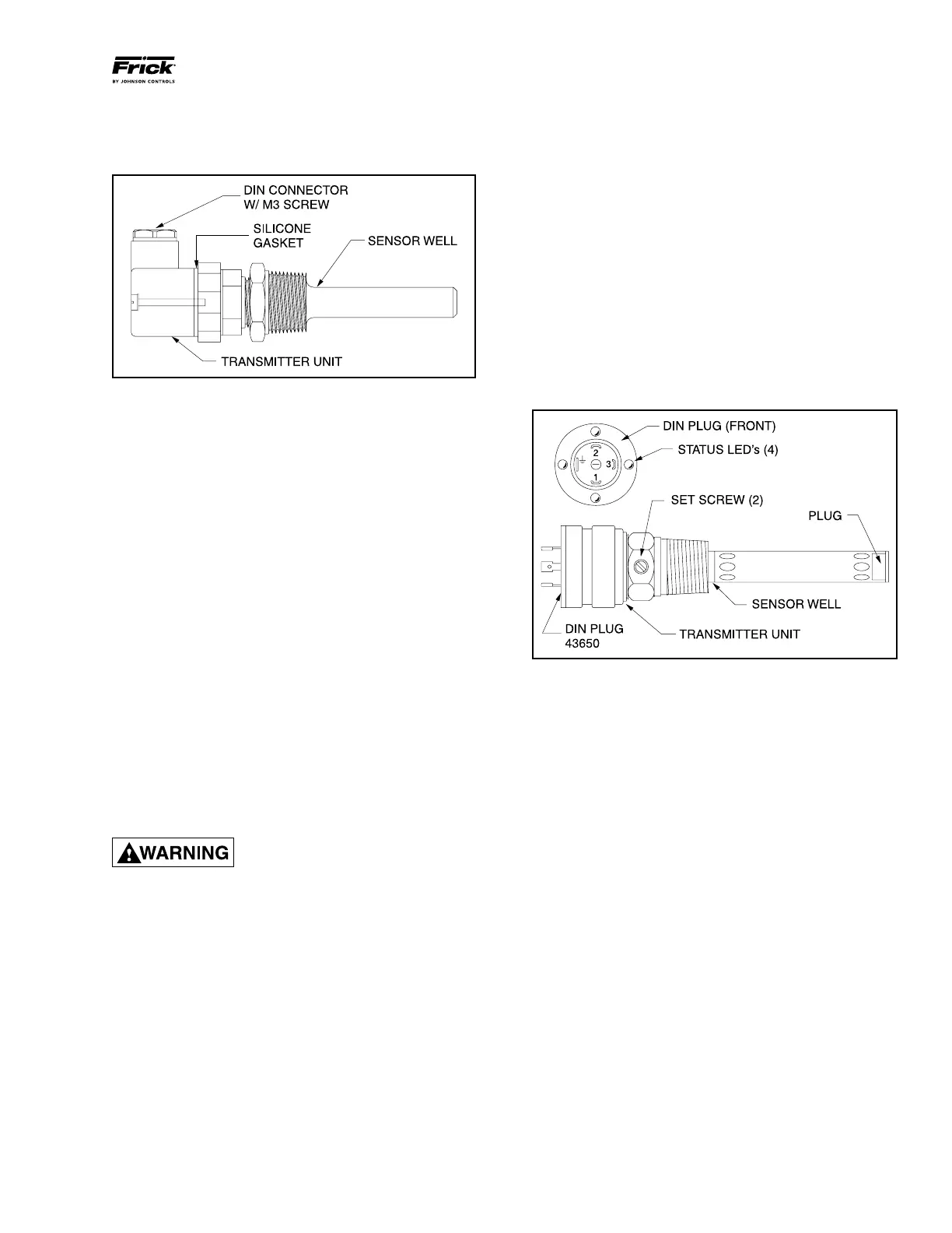
Figure 41 - OIL LEVEL TRANSMITTER
 Loading...


