RWF II ROTARY SCREW COMPRESSOR UNITS
INSTALLATION
070.610-IOM (JUN 11)
Page 7
3. Check that the keys t the hubs and shafts properly.
4. Slide one hub onto each shaft as far as possible. It may
be necessary to use a screwdriver as a wedge in the slot to
open the bore before the hubs will slide on the shafts.
5. Hold the elastomeric gear between the hubs and slide both
hubs onto the gear to fully engage the mating teeth. Center
the gear and hub assembly so there is equal engagement on
both shafts. Adjust the space between hubs as specied in
the CH COUPLING DATA TABLE.
6. Torque the clamping bolts in both hubs to the torque value
given in the CH COUPLING DATA TABLE. DO NOT USE ANY
LUBRICANT ON THESE BOLTS.
OIL PUMP COUPLING
Compressor units with direct motor/pump coupled pumps
need no pump/motor coupling alignment since this is main
tained by the closecoupled arrangement.
HOLDING CHARGE AND STORAGE
Each RWF II compressor unit is pressure and leak tested at
the factory and then thoroughly evacuated and charged with
dry nitrogen to ensure the integrity of the unit during shipping
and short term storage prior to installation.
NOTE: Care must be taken when entering the unit to
ensure that the nitrogen charge is safely released.
Holding-charge shipping gauges on
separator and external oil cooler are
rated for 30 PSIG and are for check-
ing the shipping charge only. They must be removed
before pressure testing the system and before charging
the system with refrigerant. Failure to remove these
gauges may result in catastrophic failure of the gauge and
uncontrolled release of refrigerant resulting in serious
injury or death.
All units must be kept in a clean, dry location to prevent
corrosion damage. Reasonable consideration must be given
to proper care for the solidstate components of the mi
croprocessor. Please contact Frick
®
service for long term
storage requirements.
COMPRESSOR UNIT OIL
DO NOT MIX OILS of different
brands, manufacturers, or types.
Mixing of oils may cause excessive
oil foaming, nuisance oil level cutouts, oil pressure loss,
gas or oil leakage and catastrophic compressor failure.
NOTE: The Frick oil charge shipped with the unit is the
best suited lubricant for the conditions specied at the
time of purchase. If there is any doubt due to the refrig-
erant, operating pressures, or
temperatures, refer to Frick Oil
publication 160-802 SPC.
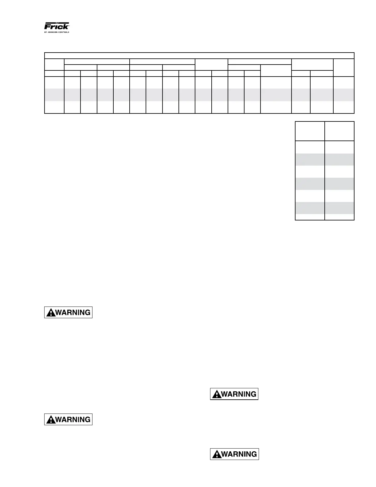
OIL CHARGE
The normal charging level is
midway in the top sight glass
located midway along the oil
separator shell. Normal operat-
ing level is midway between the
top sight glass and bottom sight
glass. The table gives the approxi
mate oil charge quantity.
Add oil by attaching the end of a
suitable pressure type hose to the
oil drain valve, located under the
oil separator. Using a pressure
type pump and the recommended
Frick
®
oil, open the drain valve and
pump oil into the separator. NOTE: Evacuation of the oil
separator will assist the ow of oil into the unit. Also, ll
slowly because oil will ll up in the separator faster than
it shows in the sight glass.
Oil distillers and similar equipment which act to trap oil must
be lled prior to unit operation to normal design outlet levels.
The same pump used to charge the unit may be used for
lling these auxiliary oil reservoirs.
NOTE: The sight glass located in the coalescing end of
the separator near the discharge connection should re-
main empty.
OIL HEATER(S)
Standard units are equipped with one to three 1000 watt
oil heaters, providing sufcient heat to maintain the oil
temperature for most indoor applications during shutdown
cycles to permit safe startup. Should additional heating
capacity be required because of low ambient temperature,
contact Johnson ControlsFrick
®
. The heaters are energized
only when the unit is not in operation.
DO NOT ENERGIZE THE HEATERS
when there is no oil in the unit, the
heat ers will burn out. The oil heat-
ers will be energized whenever 120 volt control power is
applied to the unit and the com pressor is not run ning,
unless the 16 amp circuit breaker in the micro enclosure
is turned off.
OIL FILTER(S)
Use of lter elements other than
Frick
®
may cause warranty claim to
be denied.
RWF II BASIC*
MODEL CHARGE
NO. (gal.)
100 45
134 45
177 90
222 90
270 120
316 120
399 120
480 130
496 190
546 130
676 220
856 220
1080 220
*Includes total in horizontal oil
separator and piping. Add 5 gal.
for oil cooler up to Model 270,
10 gal. for 316 1080.
CH COUPLING DATA TABLE
Coupling Hub
CH Between Shaft Spacing Shaft Engagement
Face Spacing
Clamp Bolt Keyway
Series
Min. Max. Min. Max.
Torque (Dry)
Size
Setscrew Torque Size
Size In. mm In. mm In. mm In. mm In. mm Ft-Lb Nm Ft-Lb Nm
UNC
6 2 50.8 2¾ 69.9 1 25.4
1ZB\zn
49.2 7/8 22.2 15 20.3 1/4-20 UNC 13 17.6 5/16-18
7
2B\zn
58.7
3M\zn
87.3 1 25.4
2C\zn
55.6
1Z\zn
27.0 30 40.7 5/16-24 UNF 13 17.6 5/16-18
8
2>\zn
65.1 4 101.6
1Z\zn
27.0 2½ 63.5
1Z\,
28.6 55 74.6 3/8-24 UNF 13 17.6 5/16-18
9
3Z\zn
77.8
4B\,
117.5
1M\zn
36.5 3 76.2
1M\zn
36.5 55 74.6 3/8-24 UNF 13 17.6 5/16-18
10
3>\zn
90.5 5¼ 133.4
1ZZ\zn
42.9 3½ 88.9
1ZZ\zn
42.9 130 176.3 1/2-20 UNF 13 17.6 5/16-18
11
4Z\,
104.8
5M\,
149.2
1M\,
47.6 4 101.6
1M\,
47.6 130 176.3 1/2-20 UNF 13 17.6 5/16-18
 Loading...


