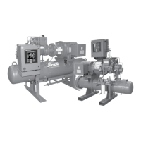
RWF II ROTARY SCREW COMPRESSOR UNITS
MAINTENANCE
070.610-IOM (JUN 11)
Page 26
Excessive pressure from expanding
refrigerant trapped between stop
valve and solenoid may cause gasket
and O-ring failure and uncontrolled refrigerant release.
3. Close service valve located between the compressor and
the liquid injection thermovalve.
4. Carefully loosen capscrews securing the strainer cover
to the strainer. Allow pressure to relieve slowly.
5. When all entrapped refrigerant has been relieved, care
fully remove loosened capscrews (as liquid refriger ant is
sometimes caught in the strainer), strainer cover and strainer
basket.
6. Wash the strainer basket and cover in solvent and blow
clean with air.
7. Reassemble strainer.
8. Open service valve between compressor and liquid injec
tion thermovalve and check for leakage.
9. Screw out manual solenoid valve stem.
10. Carefully open liquid supply service valve.
11. Leak test.
12. Close disconnect switches for compressor and oil pump
motor starters.
13. Start unit.
COALESCER FILTER ELEMENT(S)
When changing the coalescer lter element(s) it is recom
mended that the oil be changed, cartridge(s) in oil lters
OF1 and OF2 if applicable be changed and the following
applicable strainer elements be removed and cleaned.
Use of lter elements other than
Frick
®
may cause warranty claim to
be denied.
1. Refer to CHANGING OIL, Steps 1 through 8.
2. Loosen manway cover retainer bolts, remove retainers,
manway cover and cover gasket. Discard cover gasket.
3. Remove and retain nut securing coalescer lter retainer.
4. Remove retainer, coalescer lter element and 2 Orings.
Discard lter elements.
5. Install new coalescer lter element(s). NOTE: Frick Super-
Coalescer
™
element (with drain feature) must be installed
with the "DRAIN DOWN" tag on the bottom at the 6 o'clock
position.
Seat element in center of locating
tabs on separator bulkhead.
6. Replace coalescer lter retainer and nut. Tighten the nut
to 21 ft/lb torque. DO NOT OVERTIGHTEN NUT. Excessive
torque can damage the element and result in oil carryover.
Install jam nut and tighten.
7. Install new manway gasket and replace manway cover.
8. Tighten manway bolts. NOTE: RE TIGHTEN AFTER THE
COM PRESSOR UNIT IS REPRESSURIZED, SINCE MANWAY
BOLTS WILL LOOSEN.
9. Refer to CHANGING OIL, Steps 9 through 14.
CHANGING OIL
DO NOT MIX OILS of different
brands, manufacturers, or types.
Mixing of oils may cause excessive
oil foaming, nuisance oil level cutouts, oil pressure loss,
gas or oil leakage and catastrophic compressor failure.
Shut down the unit when changing oil. At the same time all
oil lter cartridges must be changed and all oil strainer ele
ments removed and cleaned. The procedure is as follows:
1. Press the [STOP] key on the microprocessor panel to
stop the compressor unit.
2. Open the disconnect switch for the compressor motor
starter.
3. Close the suction and discharge service valves; also
close the liquidinjection and economizer service valves, if
applicable.
4. SLOWLY vent separator to lowside system pressure
using the bypass line on the suction trap. NOTE: Recover
or transfer all refrigerant vapor, in accordance with local
ordinances, before opening to atmosphere. The separator
MUST be equalized to atmospheric pressure.
Oil-entrained refrigerant may vapor-
ize, causing a separator pressure
increase. Repeat venting and recov-
ery procedure, if necessary.
5. Open the drain valve(s) located on the underside of the
separator and drain the oil.
6. Drain the oil lter(s) OF1 and, if ap plicable, the oil coolers
and lter OF2.
7. Remove the old lter cartridges, then install new ones
(as previously described in the section OIL FILTER (OF-1)
MAIN SINGLE/DUAL).
8. Remove, clean, and reinstall strainer elements in the
strainers.
9. Evacuate unit to 29.88" Hg (1000 microns) vacuum.
10. Open the suction service valve and pressurize the unit
to system suction pressure. Close the suction valve and leak
test.
11. Add oil by attaching a suitable pressuretype hose to the
oil drain valve located under the separator. Using a pressure
type oil pump and recommended Frick
®
oil, open the drain
valve and ll the separator until the oil level is midway in the
top sight glass. NOTE: Evacuation of the oil separator will
assist the ow of oil into the unit. Also, ll slowly because
oil will ll up in the separator faster than it shows in the
sight glass. Refer to the table in the OIL CHARGE section
for approximate oil charge quantities.
12. Open the suction and discharge service valves, and also
the liquid injection and economizer service valves, if ap
plicable.
13. Close the disconnect switch for the compressor motor
starter.
14. Start the unit.

 Loading...


