RWF II ROTARY SCREW COMPRESSOR UNITS
OPERATION
070.610-IOM (JUN 11)
Page 21
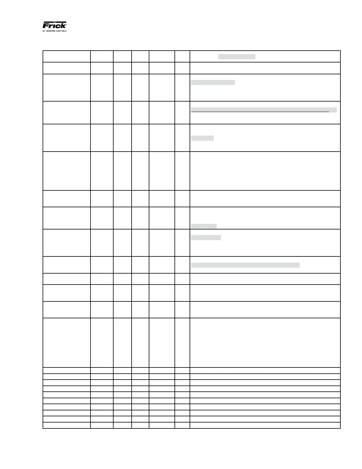
Description
Display
Name
Min. Max.
Factory
Setting
Unit
Comments (Standard Setting)
ICM OD
(Opening Degree)
- 0 100 %
ICM valve Opening Degree is displayed during normal operation.
Running display value (see j01, j05).
Main Switch j01 1 2 1
Internal main switch
1: Normal operation
2: Manual operation. Valve Opening Degree will be ashing. With the
down arrow and the up arrow push buttons the OD can be entered
manually.
Mode jo2 1 2 1
Operation mode
1: Modulating - ICM positioning according to Analogue input (see j03)
2: ON/OFF operating the ICM valve like an ON/OFF solenoid valve
controlled via Digital Input. See also j09.
Analog Input signal j03 1 4 2
Type of Analog input signal from external controller
1: 020mA
2: 4-20mA
3: 010V
4: 210V
Speed at ON/OFF
and Modulating Mode
j04 1 100 100 %
Speed can be decreased. Max. speed is 100 %
Not active when j01 = 2
If j02 = 2, the display will indicate speed in display. Low, Med, and
High also means ON/OFF operation.
If j04 < = 33, Low is displayed
33 < If j04 < = 66, Med is displayed
If j04 > = 67, High is displayed
Automatic calibration j05 0 1 0
Not active before j26 has been operated.
Always auto reset to 0.
CA will ash in the display during calibration.
Analog Output signal j06 0 2 2
Type of A0 signal for ICM valve position
0: No signal
1: 0 20mA
2: 4 - 20mA
Failsafe j07 1 4 1
Dene condition at power cut when failsafe is installed.
1: Close valve
2: Open valve
3: Maintain valve position
4: Go to OD given by j12
Digital Input function j09 1 2 1
Dene function when Dl is ON (short circuited Dl terminals) when j02 = 2
1: Open ICM valve (Dl = OFF = > Close ICM valve)
2: Close ICM valve (Dl = OFF = > Open ICM valve)
Password j10 0 199 0
Enter number to access password protected parameters:
j26
Old Alarms j11 A1 A99
Old alarms will be listed with the latest shown rst. Alarm list can be
reset by means of activating down arrow and up arrow at the same
time for 2 seconds.
OD at powercut j12 0 100 50
Only active if j07 = 4
If failsafe supply is connected and powercut occurs, ICM will go to
entered OD.
ICM conguration j26 0 6 0
NB: Password protected. Password = 11
At rst startup, A1 will ash in display. Enter valve type.
0: No valve selected. Alarm A1 will become active.
1: ICM20 with ICAD 600
2: ICM25 with ICAD 600
3: ICM32 with ICAD 600
You must get number off Valve Body
4: ICM40 with ICAD 900
5: ICM50 with ICAD 900
6: ICM65 with ICAD 900
OD% j50 0 100 % ICM valve Opening Degree is displayed during normal operation.
AI [mA] j51 0 20 mA Analog input signal
AI [V] j52 0 10 V Analog input signal
AO [mA] j53 0 20 mA Analog output signal
Digital Input function j54 0 1 Digital Input signal
DO Close j55 0 1 Digital Output Closed status. ON when OD < 3%
DO Open j56 0 1 Digital Output Open status. ON when OD > 97%
DO Alarm j57 0 1 Digital Output alarm status. ON when an alarm is detected
MAS mP SW ver. j58 0 100 Software version for MASTER Microprocessor
SLA mP SW ver. j59 0 100 Software version for SLAVE Microprocessor
Parameter list
}
 Loading...


