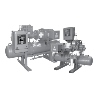
RWF II ROTARY SCREW COMPRESSOR UNITS
INDEX
070.610-IOM (JUN 11)
Page 64
Index
condensing pressure, 8
condensing tempera ture, 8
Conduit, 54
cone/button, 8
constant speed starters, 54
control power regulator, 13
control power transformer, 12
control transformer, 12
coolers, 5
cooling tower water, 9
cooling water, 9
coupling, 11
Coupling Data Table, 6
coupling hubs, 6
CPT, 12
crane, 5
CT, 12
CT ratio, 13
Current Transformer, 12
cutout parameters, 15
cycle time, 16
D
Daisychaining, 56
"D" Flange adapter, 14
dead band, 16
demand oil pump strainer, 25
Demand Pump
Assembly, 28
ball bearing, 27
single row ball bearing, 28
bearing retainer washer, 27,28
bearing spacer, 27,28
bearing spacer collar, 29
carbongraphite bushings, 27,28,29
casing, 27
demand pump, 14,15
Disassembly, 27
End Clearance, 29
idler, 27
idler pin, 27,28
lip seal, 27,29
Mechanical Seal, 28
Oring gasket, 28
Preventative Maintenance
end clear ance, 30
end clearance adjustment, 30
grease, 30
lubrication, 30
packing adjustment, 30
pump head, 28
refrigeration oil, 28
seal face, 28
seal seat, 28
seal spring, 28
shaft snap ring, 28
snap ring, 27,28
tapered installation sleeve, 28
thrustbearing assembly, 27,29
Thrust Bearing Adjustment, 29
Troubleshooting
bent shaft, 30
cavitating, 30
cavitation, 29
Discharge Port, 29
Discharge pressure, 30
discharge valve, 30
Fluttering, 29,30
Gate valve, 29
Grease leaks from vent port, 40
High viscosity, 29
Insufcient oil pressure, 40
jumping, 29
Main lter PSID too high, 40
misalignment, 29,30
Noise and Vibration, 40
Oil pressure drops as head pressure
increases, 40
Oil pressure uctuates, 40
Oil pressure rapidly drops, 40
Pressure Gauge, 29
Relief valve, 29
Relief valve poppet, 30
Starving, 30
Strainer, 30
suction port, 29
Suction valve, 30
vacuum gauge, 29
Vibrating, 30
Viking Pump, 27
demand pump, 14,15
disctype check valves, 11
discharge check valve, 15,22
discharge pressure, 14
disconnect switches, 24
disc drive spacer, 6
disc packs, 6
doubleacting hydraulic cylinders, 16
DoubleActing Mode, 16
doubleacting solenoid valve, 17
drain valve, 25
drive coupling, 22
drive hubs, 6
dry nitrogen, 7,24
dualport liquid injection, 16
dualsetpoint, 11
dual dip tube method, 9
dual oil lters, 14
DX economizer, 10
DX vessel, 11
E
Economizer
backpressure regulator valve, 10,11
balancing load, 11
BPR valve, 11
check valve, 11
DX economizer, 10
DX vessel, 11
economizer port, 10,11
economizer vessel, 11
electric shutoff option, 11
Symbols
3phase ground, 54
3phase supply, 54
A
Abnormal Operation Analysis and Cor
rection, 33
acrosstheline, 12
atmospheric pressure, 25,26
axial loads, 14
axial load bearings, 14
B
backfeeding, 22
back ushing, 10
backpressure regulator, 11
backpressure regulator valve, 10,11
balance piston, 14,22
Balance Piston Pressure Regulator, 30
balancing load, 11
bleed valve, 25
booster application, 12,15
booster compressor, 22
booster systems, 22
BP, 16
BP coupling data table, 6
BPR valve, 11
brownouts, 13
C
cable trays, 54
CH Coupling Data Table, 7
check valve, 11,22
chemical cleaning process, 9
circuit breaker, 12
circuit breaker disconnect, 12
clamping bolts, 7
closedloop uids, 9
closedloop system, 9
coalescer lter element, 15,26
coalescer lter retainer, 26
codes, 54
ColdStart System, 15
coldstart valve, 15,34
Comm Port Protection, 56
Communications, 56
Compressor
compressor, 11
discharge, 15
drive shaft, 14
hydraulic system, 16
lubrication, 15
motor, 11,12
oil tempera ture, 16
suction, 16
Vi, 16
Compressor Operating Log Sheet, 62
Compressor Port Locations, 41
condenser, 15
condenser inlet, 8

 Loading...


