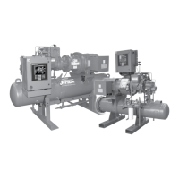
RWF II ROTARY SCREW COMPRESSOR UNITS
INDEX
070.610-IOM (JUN 11)
Page 66
liquid solenoid, 10,25
liquid supply service valve, 25
locknut, 6
low differential oil pressure, 15
low pressure transducer, 25
low voltage, 11
lubrication system, 14
M
magnetic eld, 54
Maintenance
Abnormal Operation Analysis and
Correction, 33
abnormal system conditions, 33
abnormal vibration, 30
Capacity Linear Transmitter, 36
compressor unload cylinder, 36
condensed refrigerant, 34
DIN connector plug, 36
lter elements, 31
Grease Compatibility, 32
leaks, 30
linear transmitter, 36
lubrication, 32
Lubrication Schedule, 32
Maintenance Schedule, 31
Main Operating Screen, 33
moisture, 31
Motor Bearings, 32
NLGI Grease Compatibility Chart, 32
noise, 30
oilbase grease, 32
oil analysis, 31
oil level control, 37
Oil Level Transmitter, 37
Oil quality, 31
Operating Log, 32
Potentiometer, 36
Pressure Transducers
discharge pressure, 35
discharge pressure transducer, 35
oil pressure transducer, 35
Pressure Transducer, 35
Replacement, 35
Testing, 35
transducer isolation valve, 35
voltage reading, 35
Proper Installation of Electronic Equip
ment, 52
P & I Diagram, 49
Recommended Maintenance Program,
30
refrigeration oil, 31
sensor well, 36
Servicing the ColdStart Valve, 34
bonnet, 34
Bonnet Cap Screw Torque Values,
34
valve body, 34
valve housing, 34
stop valve, 34
Temperature Transmitter, 37
Troubleshooting.
See Index, Trouble
shooting
Troubleshooting Guide, 33
Vibration Analysis, 30
Vibration Data Sheet, 63
vibration readings, 30
volume ratio control, 36
Volumizer® unit, 36
main oil injection port, 15
manual solenoid, 26
manway bolts, 26
manway cover, 26
microprocessor, 10,11,16,17
microprocessor control system, 12
mist, 15
motor, 11
Motor And Bare Compressor
Replacement, 40
motor contactor, 11
motor rotation, 6
motor starters, 24
motor starter coils, 12
motor starter contactor, 11
mounting bolts, 5
movable slide stop, 16
movable slide valve, 14,16
MSS, 16
MSV, 16
MSV solenoid, 16
N
neoprene drive spacer, 6
nitrogen charge, 7
O
dual oil lters, 25
main oil lter, 25
oil, 5
oilcharging valve, 26
Oilentrained refrigerant, 26
Oil Charge, 7
oil charge reser voir, 15
oil cooler, 9,14
oil lters, 24
oil lter cartridges, 26
oil foaming, 7,25,26,31
oil heaters, 7,12
oil leakage, 7,25,31
oil level cutout, 7,25,26,31
Oil Level Transmitter
Replacement, 37
Troubleshooting, 36
Din Plug, 37
oil manifold, 16,22
oil pressure loss, 7,31
oil pump, 14,15
Oil Pump Coupling, 7
oil pump starter, 12
oil sampling valve, 32
oil seal, 14
oil separator, 11,14,15
oil strainer elements, 26
Oil temperature, 8
operating level, 7
Operating Log Sheet, 57
operating volume ratio, 17
Optical Isolation, 56
ORIFICE, 23
outlet pressure regulator, 11
overpressurizing, 11
P
Packaged Refrigerant Recirculation unit,
11
package vibration, 5
partial load, 11
pH, 9
pipe hangers, 5
piston, 15
pistontype check valves, 11
plate and shell oil cooler, 8
plate and shell type thermosyphon oil
cooler, 8
PointToPoint Wiring Diagram, 13
port pressure, 10
power feed, 54
power uctuations, 13
premature bearing failure, 24
PRESSUREREGULATING VALVE, 22
pressure differential, 15
proportional band, 16
no pump, 14
pumpout connection, 22
purge valve, 25
P & I DIAGRAM, 49
PVC conduit, 54
Q
Quantum™LX, 3,11,15,24,56
R
reboot, 56
receiver, 8,9
refrigerant charge, 5
refrigerant isolation valves, 9
refrigerant vapor, 26
refrigeration oil, 25
regulating control transformer, 12
roller bearings, 14
Rotary Screw Compressor, 5
rotor contact, 14
S
safety valve, 9
Sales Order Numbers, 3
SC2, 16
scaling, 9
selflubricating, 14
separator, 5,7,26
serial number, 4
service valves, 26
setpoint, 11,16
severe water conditions, 9
SGC Compressor, 14

 Loading...


