Callout Description
1 Terminal on the first device
2 Terminal on the daisy-chained device
3 Connection to another device on the RS-485
bus
4 Cable shield connection. You do not need to
ground the cable shield.
5 Connection from another device on the
RS-485 bus
UI jumper setting
The FW-14 UI jumper includes 16 sets of UI and supports
both resistance and voltage field devices.
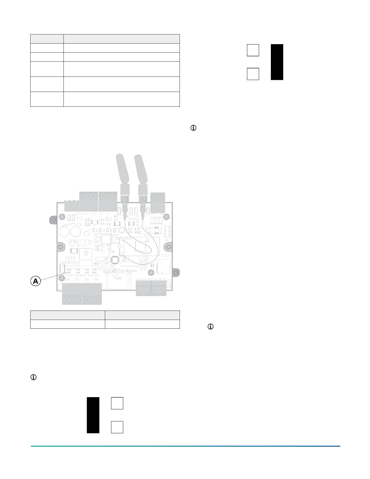
Figure 20: FW-14 front uncovered
Callout Component
A Universal input
Universal input jumper configuration
The FW-14 controller supports resistance and voltage field
devices. For resistance mode, position the jumper on the
two left pins. For voltage mode, position the jumper on
the two right pins.
Note: You can configure each UI individually.
Figure 21: Resistance mode
Figure 22: Voltage mode
Controller interfacing
To interface with a controller and its inputs and outputs
with CPT and the controller's web server, establish a
connection from your device. You can connect to your
controller with a device through Ethernet or though Wi-Fi.
Note: Use the following procedures to set up
a controller on a primary network. For more
information about a secondary network setup, refer
to the product's User Reference Guide.
• To connect to your controller with a computer
or laptop by using an Ethernet LAN cable, see
Connecting a controller with an Ethernet cable.
• To connect to your controller with a mobile device,
computer, or laptop with Wi-Fi, see Connecting to a
controller with Wi-Fi.
Interface with your controller with the following user
interfaces:
• Access the controller dashboard and make network,
DateTime, and service configuration changes on the
controller's web server. For more information, see
Interfacing with a controller's web server.
• Program controller object logic with CPT. For more
information, see Interfacing with controller objects
using CPT.
Connecting a controller with an
Ethernet cable
1. Connect your computer to the controller with an
Ethernet cable.
2. Set up your network adapter in the same range as
the controller. To change your IP address, subnet
mask, and gateway, complete the steps as outlined
in one of the following options, depending on your
operating system:
Note: Use the same subnet mask and
gateway as the controller. For the IP address,
enter the same IP address as the controller,
but change the last octet to a unique number.
Use a high number that is less than 255 to
avoid using an IP address that is already
in use. For more information about your
controller's IP address, subnet mask, and
gateway, see Primary network default IP
address, subnet mask, and gateway.
Connecting to a controller with Wi-Fi
1. From the desktop toolbar on your computer, click
your Wi-Fi network icon.
2. Find the controller's SSID, then connect to the
controller.
FW-14 Quick Start Guide8