Johnson Controls, Inc. SLC Wiring Manual — P/N 51870:G 04/23/2009 29
Isolator Detector Bases SLC Circuits with Isolators
5.3 Isolator Detector Bases
Isolator detector bases prevent an entire communications loop from being disabled when a short
circuit occurs. This is accomplished by isolating that part of the loop containing the short from the
remainder of the circuit. These bases also automatically restore the entire loop when the cause of
the short circuit is corrected.
B224BI is an intelligent isolator base used with FlashScan® detectors and most CLIP mode
detectors.
5.3.1 How an Isolator Base Works
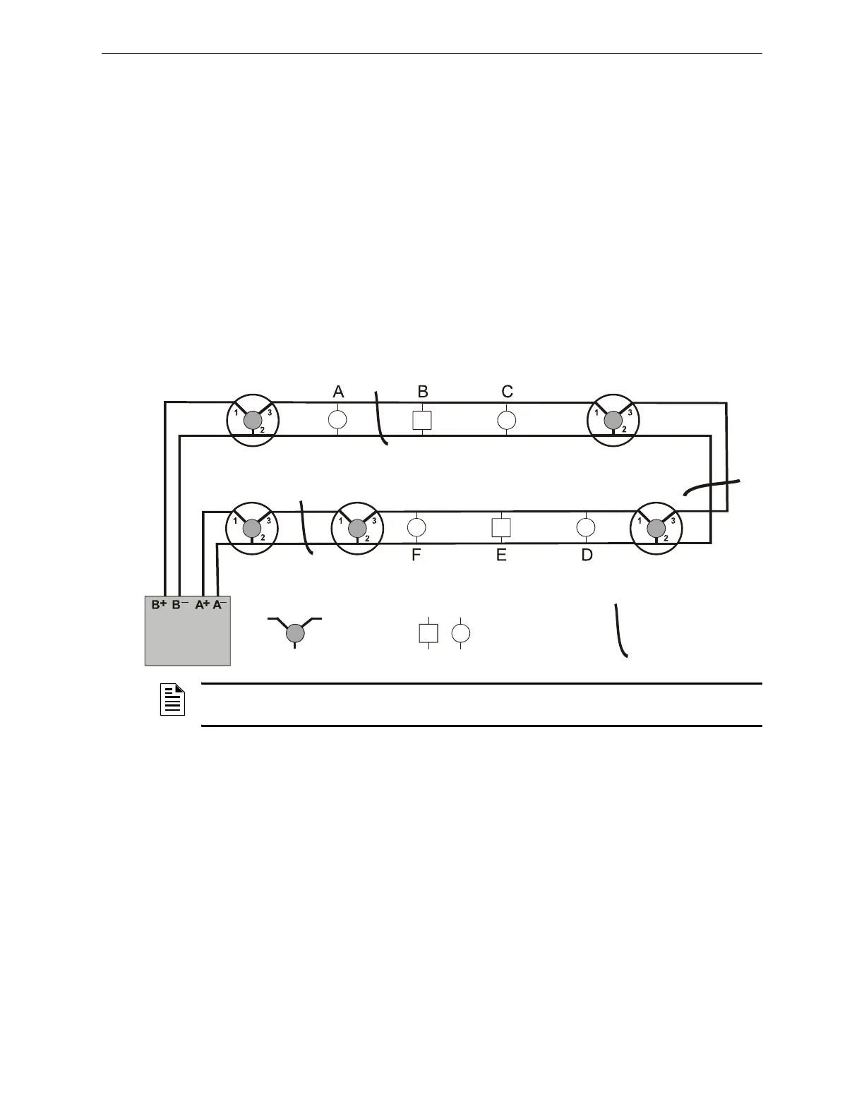
If a short circuit fault occurs at point “X”, devices A, B, C & detector 2 will cease to function and
display a trouble warning at the control panel. Devices D, E, F & detectors 1, 3, 4, and 5 will
remain normal as they are served by ‘SLC Return’.
If a short circuit fault occurs at point “Y”, all devices will continue to function.
If a short circuit fault occurs at point “Z”, only detector 4 will cease to function.
Figure 5.2 Isolator Base Circuit: Sample Style 6 Wiring
Non-Isolating DeviceIsolator Base
X
Z
Control Panel
SLC Return
SLC Out
SLC-isowork.wmf
Detector 1
Detector 2
Detector 3
Detector 4
Detector 5
Y
Short-circuit path
NOTE: For information on wiring an isolator base, refer to Figure 9.3, “Wiring an Isolator Base”
on page 50.
 Loading...
