Johnson Controls, Inc. SLC Wiring Manual — P/N 51870:G 04/23/2009 37
NFPA Style D IDC Using Monitor Modules Monitor Modules
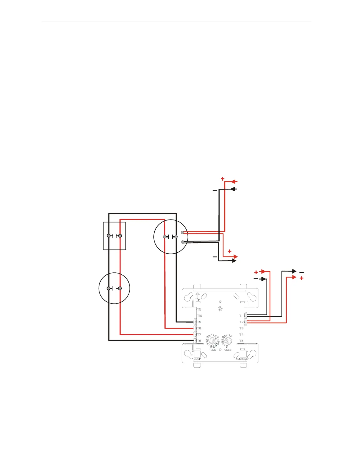
6.4 NFPA Style D IDC Using Monitor Modules
Connect the SLC wiring to the module terminals 1 (–) and 2 (+).
Each M300MJ module takes one address on the SLC. Use the rotary switches on the module to set
it to the required SLC address.
Figure 6.8 shows typical wiring for a supervised and power-limited NFPA Style D (Class A) IDC
using the M300MJ module.
Module installation notes:
1. The Initiating Device Circuit (IDC) is supervised and current-limited to 210 microamps
@ 24 VDC (nominal).
2. The IDC provides the following services (do not mix):
• Fire alarm service
• Automatic and manual waterflow alarm service with normally open contact devices
• Sprinkler supervisory service with normally open contact devices
• Security service
3. Refer to the Device Compatibility Document for compatible smoke detectors.
4. See “Power Considerations” on page 53 for information on supervising 24 VDC power.
Figure 6.8 Typical Style D IDC Wiring with M300MJ
SLC-idcD1tpH.wmf
24 VDC
Four-wire
Detector Base
Heat
detector
SLC
IDC
24 VDC Power
Filtered, Regulated,
Resettable
From
Supply
To Next IDC
or
Supervision Device
Manual pull
station