50 Johnson Controls, Inc. SLC Wiring Manual — P/N 51870:G 04/23/2009
Intelligent Detector Bases Wiring an Isolator Base
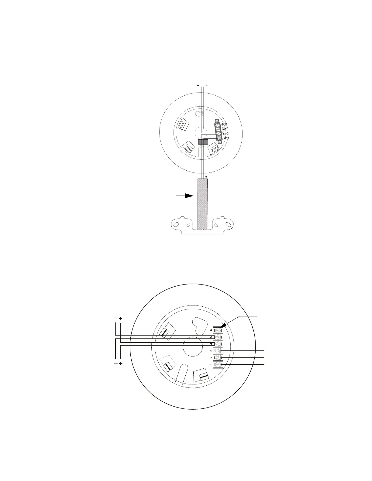
9.3 Wiring an Isolator Base
The Isolator Base will isolate its detector from short circuits that occur on the SLC connected at
terminals 3 and 2. It will not isolate its installed detector from short circuits that occur on the SLC
connected at terminals 1 and 2. In Style 7 applications, the loss of a single detector during a short
circuit is not acceptable, and an isolator module must be installed as shown in the figure below.
Figure 9.3 Wiring an Isolator Base
9.4 Wiring a Relay Base
Figure 9.4 shows typical wiring of the B224RB plug-in relay detector base connected to an SLC.
Figure 9.4 Wiring of the B224RB Plug-in Relay Detector Base
SLC In
SLC Out
SLC-224BIwire.wmf
Conduit
M500XJ
Isolator Module
SLC
b224rb.wmf
To next device
on SLC
For connection of
cable shield
3
R
e
l
a
y
C
o
m
m
o
n
2
N
o
r
m
a
l
l
y
O
p
e
n
1
N
o
r
m
a
l
l
y
C
l
o
s
e
d