60 Johnson Controls, Inc. SLC Wiring Manual — P/N 51870:G 04/23/2009
SLC Surge Suppression Installation
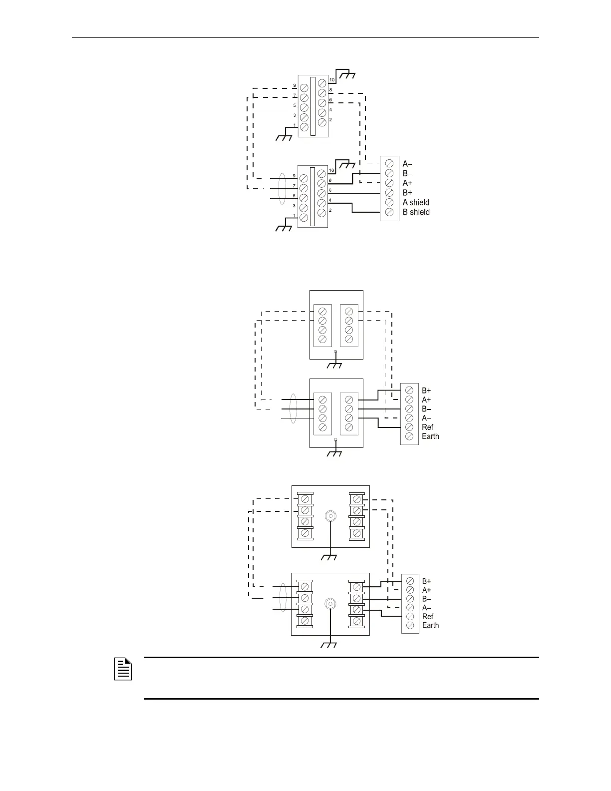
SLCP-30 Connections
B.2.2 IFC-300, IFC-400
DTK-2LVLP-F Connections
PLP-42N Connections
IN
IN
OUT
OUT
SLCP-30
SLCP-30
+
–
SLC-slcp1.cdr
SLC Terminal Block
SLC Loop
Optional Four-wire Return Loop
Style 6 (Class A)
IN
IN
OUT
OUT
2LVLP-F
2LVLP-F
+
–
SLC-lvlp2.cdr
SLC Loop
SLC Terminal Block
Optional Four-wire Return Loop
Style 6 (Class A)
–
+
INPUT
OUTPUT
PLP-42N
L1 L2 L3 L4
L1 L2 L3 L4
GRND
INPUT
OUTPUT
PLP-42N
L1 L2 L3 L4
L1 L2 L3 L4
GRND
SLC-plpn2.cdr
SLC Loop
SLC Terminal Block
Optional Four-wire Return Loop
Style 6 (Class A)
NOTE: Use 12 AWG (3.31 mm
2
) to 18 AWG (0.82 mm
2
) wire with crimp-on connectors to
connect the unit’s ground terminal to equipment ground. Wire length must be minimized to
provide best protection
 Loading...
