62
Hardware Installation—Installing the
IFC-1010/2020
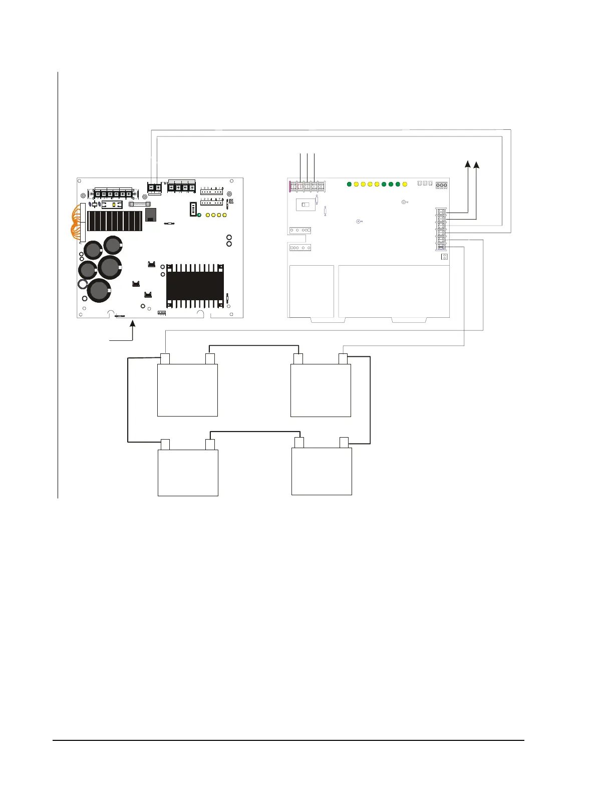
Battery –
55 AH/
60 AH
(12 V)
–
+
55 AH/
60 AH
(12 V)
–
+
55 AH/
60 AH
(12 V)
–
+
55 AH/
60 AH
(12 V)
–
+
TB2
TB1
–
+
–
+
–
+
Battery +
chgbatcx
Battery Interconnect Cable
Battery Interconnect Cable
P4
P3
JP5
TB1
TB2
F1CB1
JP2
JP1
P5
P7
R27
P2
EARTH GND AC NEUTRAL AC HOT
+24R COMMON +24 COMMON
POWER LIMITE D
BAT + BAT -
MPS- 24A EPCC REV __ _
MPS-24APCC REV ___
Charger
MPS-24A or
MPS-24AE
To Auxiliary
Equipment
AC Power In
Neut
Grd
Hot
Out 2 -
Out 1 +
Out 1 -
Out 2 +
24 VDC (supervised)
. Maximum charge current for batteries
is 4.5 amperes (fast charge) or 20mA (trickle charge). Use
12 AWG (3.25 mm²) wire in conduit ( 20 feet or less]).6.096 meters [
CHG-120
120/240VAC, 50/60 HZ
-
+
Cut JP1 to
disable
onboard charger.
Figure 40: CHG-120 Connections