Hardware Installation—Installing the IFC-1010/2020
73
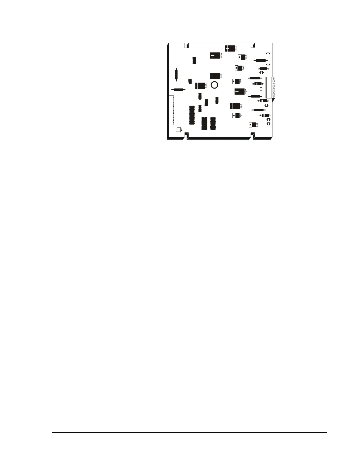
lib200
Figure 47: LIB-200
The LIB-200A field wiring is electrically isolated from the rest of the
system so that any two ground faults on separate SLCs will not cause
invalid replays from devices. A short to any other system circuit will not
cause communication loss. The LIB-200A has an earth fault detection
circuit with selectable high/low sensitivity and disable. The LIB-200A
supports up to 12,500 feet of field wiring on Ports A and B for Style 4 and
12,500 feet total for Style 6 and 7. The maximum loop resistance for style
4 is 50 ohms on Ports A and B and 50 ohms total for Styles 6 and 7. The
LIB-200A has two LEDs; yellow displays earth fault trouble and red
indicates initiated alarm condition during local mode only (refer to
Figure 48).
The LIB-400 filed wiring is electrically isolated from the rest of the system
so that any two ground faults on separate SLCs will not cause invalid
replays from devices. A short on to any other system circuit will not cause
communication loss. The LIB-400 has an earth fault has an earth fault
detection circuit with selectable high/low sensitivity and disable.
The LIB-400 supports up to 12,500 feet of field wiring on Ports A and B
for Style 4 and 12,500 for Style 6 and 7. The maximum loop resistance for
Style 4 is 50 ohms on Ports A and B and 50 ohms total for Styles 6 and 7.
The LIB-400 supports the Local Mode General Alarm Bus, a feature that
permits limited alarm function in the unlikely event of a CPU failure. The
LIB-400 has two LEDs per loop; yellow indicates an earth fault and red
indicates an alarm condition during local mode only (refer to Figure 48).
LIB-200A
LIB-400