Hardware Installation—Installing the IFC-1010/2020
77
slcstyl6
Channel A
Channel B
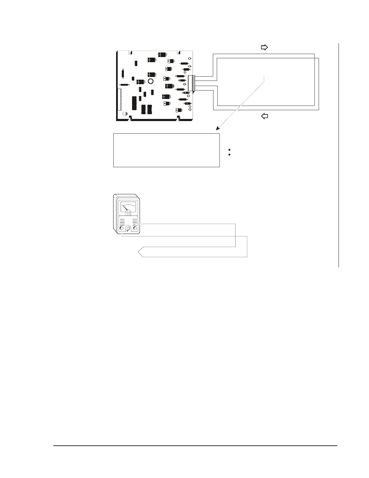
Style 6/7 SLC Loop
LIB
When T-taps are present they each represent a
Style 4 branch. These branches will not degrade
the Style 6 loop and are permissible from an
operating standpoint, but such branching will not
comply with the NFPA 72 standared for Style 6
SLC performance.
Total Length of the Style 6 SLC Loop Pair
(including and Style 4 branches):
LIB-200 - 10,000 feet
cannot exceed
LIB-200A/LIB-400 - 12,500 feet
cannot exceed
The total DC resistance from the LIB-200 panel to branch end cannot exceed 40 ohms.
The total DC resistance from the LIB-200A panel or the LIB-400 panel to branch end
cannot exceed 50 ohms.
In a simple Style 6 arrangement, this measurement may be made by disconnecting
Channels A and B at the control panel, shorting the two leads at the input of
Channel A, and metering the two leads of Channel B.
Channel B
Channel A
Figure 50: SLC Loop Wiring Requirements (Style 6)