FORM 145.05-EG2 (618)
20
JOHNSON CONTROLS
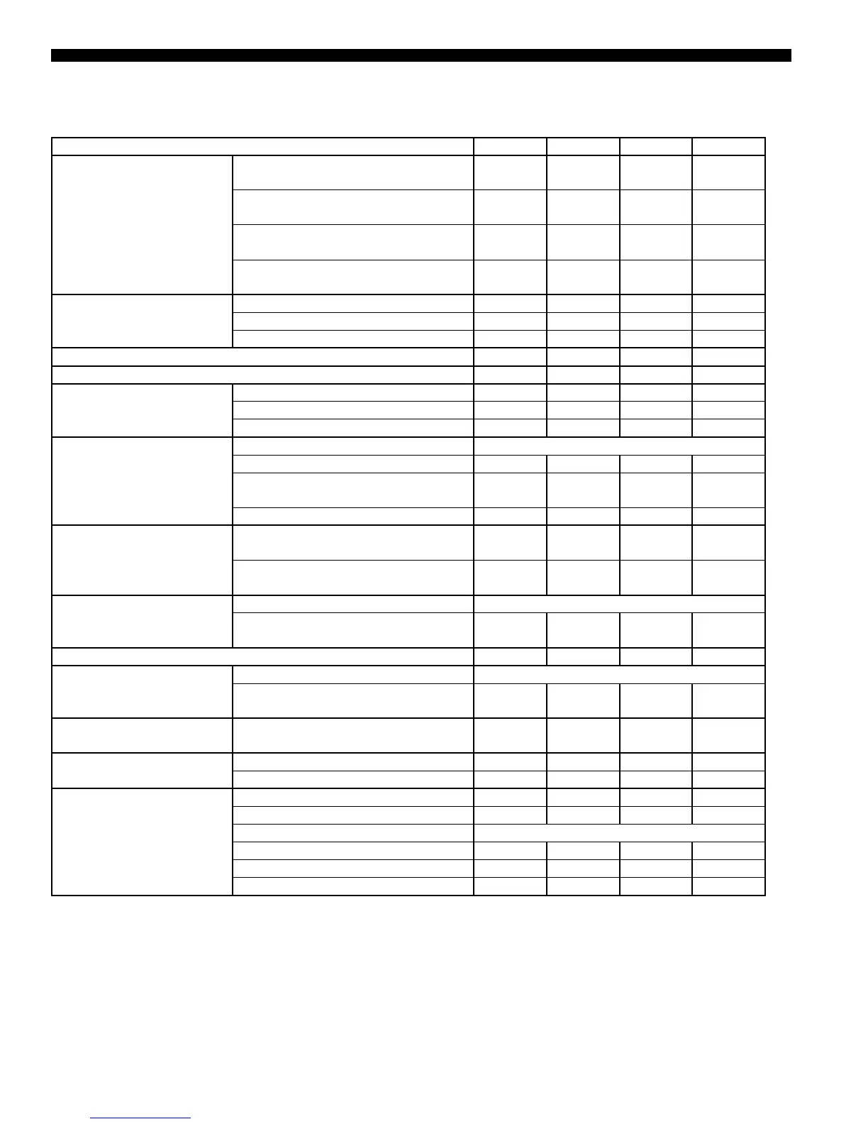
TABLE 6 - LSWU070-LSWU105
Nominal Capacity, Tons 70 80 95 105
Air Flow Range
Maximum Design Air Flow - Standard -
CFM
29,800 33,900 36,100 36,100
Maximum Design Air Flow- High
Efciency - CFM
24,800 28,200 30,100 30,100
Minimum Design Air Flow - Standard -
CFM
19,900 22,600 24,200 24,200
Minimum Design Air Flow - High
Efciency - CFM
17,400 19,800 21,200 21,200
Cabinet Dimensions
Depth (Excluding Filter Section) - Inches 96 96 96 96
Length - Inches 130 130 130 130
Height - Inches 102 102 102 102
EER 14.1 13.7 13.7 13.3
EER - High Efciency 14.5 14.1 14.1 13.7
Cooling Coil
Face Area - Square Feet 49.7 56.5 60.3 60.3
Rows 4 5 5 6
Fins Per Inch (Standard/High Efciency) 12/17 12/17 12/17 12/17
Supply Fan
Fan Type Airfoil Plenum Fan (SWSI)
Diameter - Inches/Class - Standard 36/Class II 36/Class II 40/Class II 40/Class II
Diameter - Inches/Class - High Capacity
Fan
40/Class II 40/Class II None None
Fan Motor HP 15 - 40 15 - 40 20 - 50 20 - 50
Filters
4 Inch Deep - MERV 8 20X20X4 /
24X20X4
8 / 12 8 / 12 8 / 12 8 / 12
4 Inch Deep - MERV 13 20X20X4 /
24X20X4
8 / 12 8 / 12 8 / 12 8 / 12
Compressors
Type Scroll
Compressor Quantity / Nominal HP
2 - 15 +
2 - 13
4 - 15 6 - 13 6 - 15
Number of Capacity Steps 4 4 6 6
Condensers
Type Shell and Tube
Quantity (2 refrigerant circuits per
condenser)
2 2 3 3
Condenser Water
Connections
Water In and Out Copper Victaulic
Connections - Inches
3.125 3.125 3.125 3.125
Waterside Economizer Coil
Face Area - Square Feet 49.7 56.5 60.3 60.3
Rows/Fins Per Inch 4/11 4/11 4/11 4/11
Heating
Hot Water Coil Face Area - Square Feet 35.8 40.6 43.3 43.3
Hot Water Coil Rows/Fins Per Inch 1/12 1/12 1/12 1/12
Steam Coil Consult Factory
Electric Heat - KW - 240/3/60 Nominal 17.5/35.0 17.5/35.0 35.0/52.5 35.0/52.5
Electric Heat - KW - 480/3/60 Nominal 17.5/35.0 17.5/35.0 35.0/52.5 35.0/52.5
Electric Heat - KW - 600/3/60 Nominal 17.5/35.0 17.5/35.0 35.0/52.5 35.0/52.5
Physical Data (Cont’d)
 Loading...


