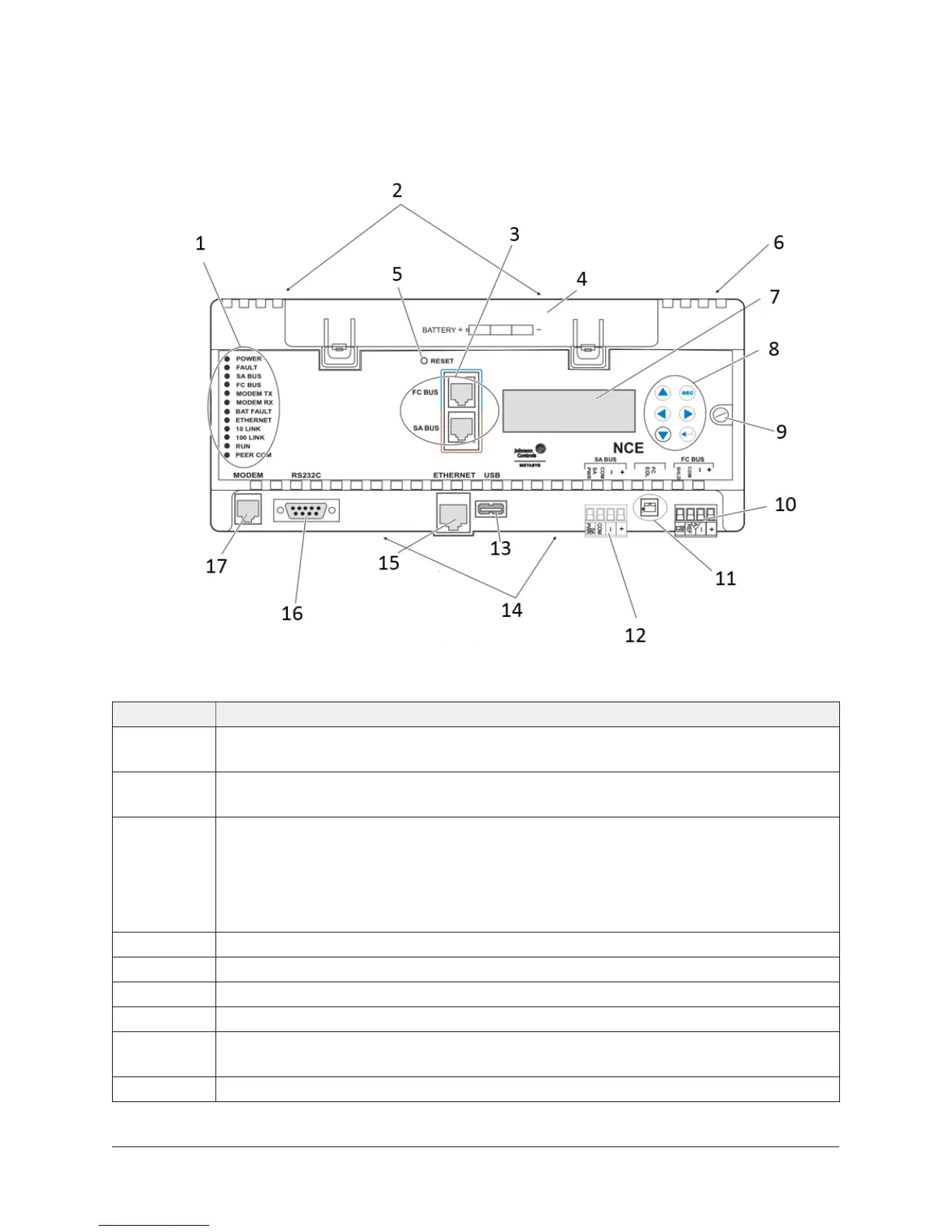
NCE25 physical features
Figure 3: Front of NCE2567-0 showing physical features (power
and I/O terminal blocks, and NCE mounting clips not shown)
Table 1: Callout table for NCE25 physical features
Callout Description
1 The LED status indicators vary depending on the NCE model. See LED status
indicators.
2 Binary output, configurable output, and analog output terminal blocks are located
on the top side of the NCE. See Input and output wiring guidelines.
3 6-Pin modular Bus ports.
• FC Bus port for MS/TP models only, connects to a Wireless Commissioning
Converter (MS-BTCVT-1).
• SA Bus port connects to a NS network sensor, a DIS1710- Local Controller Display,
or a Wireless Commissioning Converter (MS-BTCVT-1).
4 Data protection battery component.
5 NCE reset switch.
6 24 VAC Class 2 supply power terminal block is located on the top side of the NCE.
7 Display screen on specified models and displays NCE menus and commands.
8 Display navigation keyypad is used to navigate the display menus and initiate
commands.
9 Cover screw.
5NCE25 Installation Instructions

 Loading...


