VAV Controller—Variable Air Volume (VAV) Controller 57
The following table illustrates the selections made through HVAC PRO for
Windows for this example.
Note: The examples contained in this technical bulletin do not reflect all
of the possible questions and answers. These examples are
provided as a basic overview of wiring locations you might expect
to see.
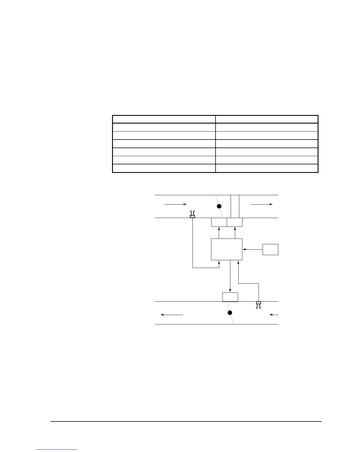
Table 20: Single Duct Wiring Example 2
Questions and Configuration Selections
HVAC PRO for Windows Questions Configuration Selections
Control Strategy
Pressure Independent
Fan Type
None
Exhaust Box Required
Yes
Baseboard Heat Type
None
Box Heat Type
Proportional
Lighting Integration
Not Available
VAV2
H
T
G
VA1DA1
C1
TE1
DPT1
DPT2
Exhaust Box
DA2
Figure 25: Single Duct Wiring Example 2
Mechanical Flow Diagram
 Loading...


