VAV Controller—Variable Air Volume (VAV) Controller 59
The following table illustrates the selections made through HVAC PRO for
Windows for this example.
Note: The examples contained in this technical bulletin do not reflect all
of the possible questions and answers. These examples are
provided as a basic overview of wiring locations you might expect
to see.
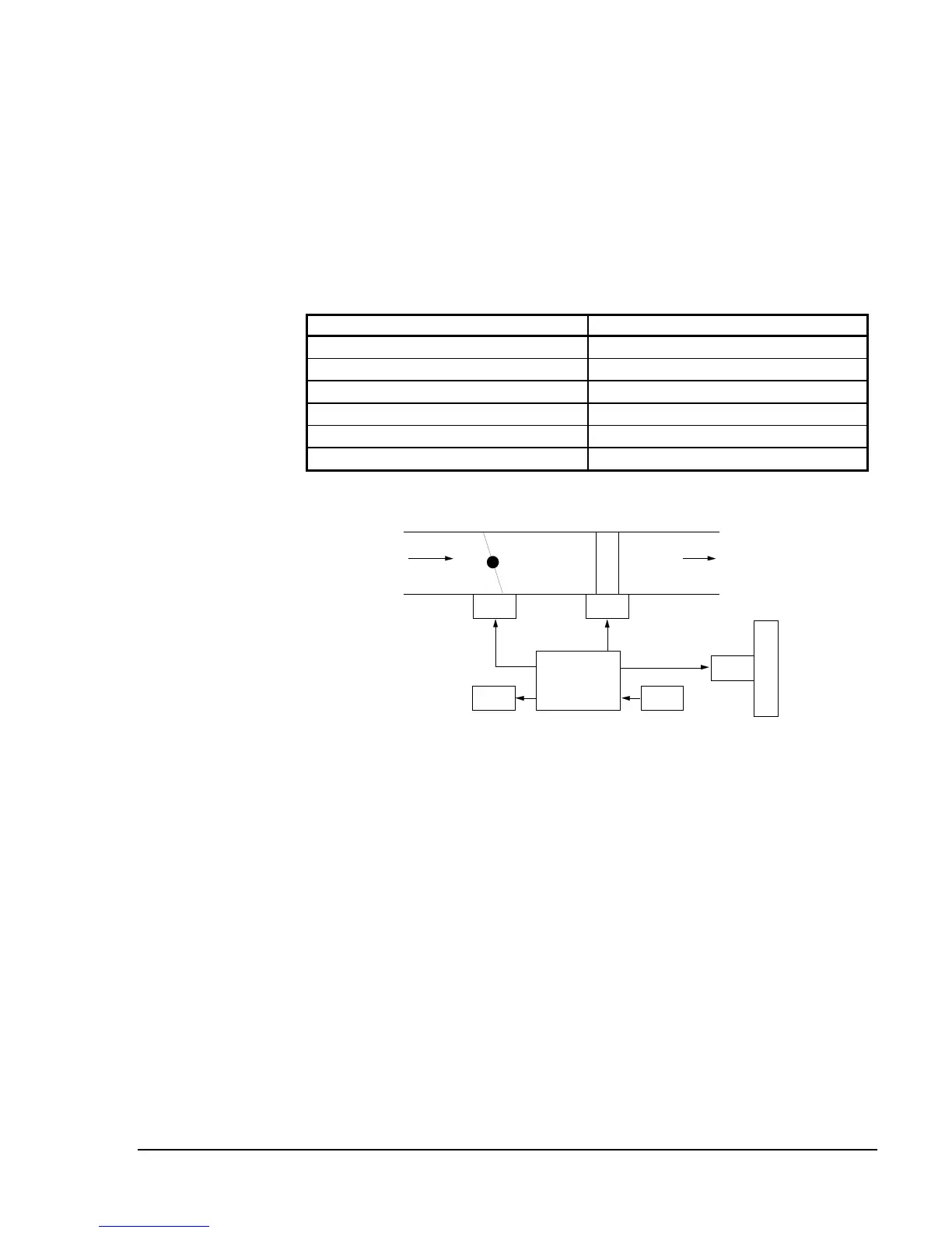
Table 22: Single Duct Wiring Example 3
Questions and Configuration Selections
HVAC PRO for Windows Questions Configuration Selections
Control Strategy
Pressure Dependent Without Feedback
Fan Type
Not Available
Exhaust Box Required
Not Available
Baseboard Heat Type
On-Off
Box Heat Type
Incremental
Lighting Integration
Yes
VAV3
B
A
S
E
B
D
TE1
C1
R1
DA1
H
T
G
VA2
VA1
Figure 27: Single Duct Wiring Example 3
Mechanical Flow Diagram
 Loading...


