System 450™ Series Modular Control Systems with Standard Control Modules Technical Bulletin22
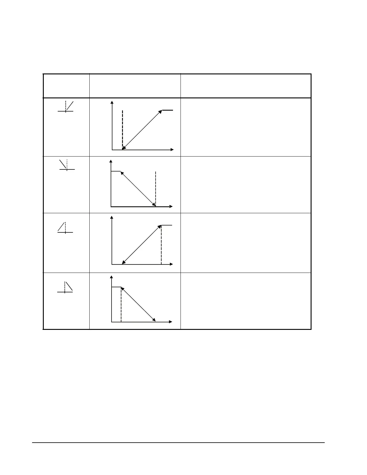
Table 4 shows the four control ramp icons and describes their corresponding
control actions and the setup value relationships required to configure the four
control actions. See Figure 23 and Figure 24 on page 52 for examples.
Table 4: System 450 Control Ramps, Analog Output Control Actions, and
System Setup Value Relationships
Control Ramp
Displayed
Control Action Set the Analog Output Value Relationships
for the Desired Control Action and
Corresponding Control Ramp
SP < EP
OSP < OEP
SP > EP
OSP < OEP
SP > EP
OSP > OEP
SP < EP
OSP > OEP
Output Minimum at SP
a
l
SP=50°
EP=60°
Output Minimum at SP
EP=50°F SP=60°F
Output Maximum at SP
EP=50°F SP=60°F
P
r
o
p
o
r
t
i
o
n
a
l
B
a
n
d
Output Maximum at SP
SP=50°F
OSP=100%
OEP=0%
P
r
o
p
o
r
t
i
o
n
a
l
B
a
n
d

 Loading...


