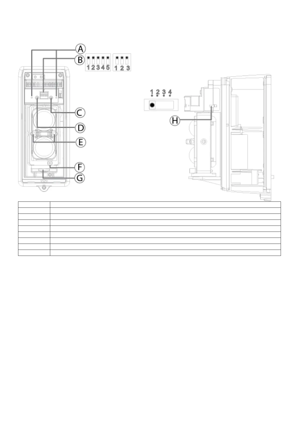
EasyManua.ls Logo

Johnson Controls PG9200AX - Device Settings; Switch Functions

Johnson Controls PG9200AX
102 pages
Print Icon
To Next Page IconTo Next Page
To Previous Page IconTo Previous Page
Loading...
D-308403 29011054R001 PG9200AX 15
Device settings
Callout
Component
A
Monitor jack (receiver only)
B
Switches
C
Receiver: Alarm indicator LED. Transmitter: Power LED
D
Low battery LED
E
View finder
F
Vertical alignment dial
G
Horizontal alignment dial
H
4-channel beam frequency selector
Switch functions
Warning: We do not recommend changing the default settings apart from the Battery saving timer. See Battery saving
timer for more information. Changing other default settings can cause the device to function incorrectly and increases
the chance of failure or false alarms.
Receiver
1 and 2: Beam interruption adjustment switch
3: Battery saving timer switch
4: Not used. Do not change the position of this switch.
5: N.C./N.O. selection switch
Transmitter
1: Battery saving timer switch
2: Not used. Do not change the position of this switch.
3: N.C./N.O. selection switch

Table of Contents

Related product manuals