12
FORM 145.10-IOM4
ISSUE DATE: 2/27/2019
SECTION 1 - INSTALLATION
2. Fully close the damper actuator by turning the
drive shaft CCW (LADK kit) or CW (VADK kit).
3. Insert the tab on the anti-rotation bracket into the
slot located on the bottom of the damper actuator.
Slide the damper actuator onto the damper drive
shaft.
4. Position the anti-rotation bracket 6-3/16 inches
below the drive shaft center (see Figure 6 on page
11.
5. Use the holes in the anti-rotation bracket as a
guide, and secure the bracket to the damper actua-
tor casing using the self-drilling screws provided.
(Do not drive screws near the center of the damper
actuator casing. Use the outermost holes in the an-
ti-rotation bracket.)
6. Adjust the anti-rotation bracket as necessary to
position the tab midway into the slot at the bottom
of the damper actuator.
The tab on the anti-rotation bracket must
t midway into the actuator slot to prevent
damper actuator binding and premature
wear.
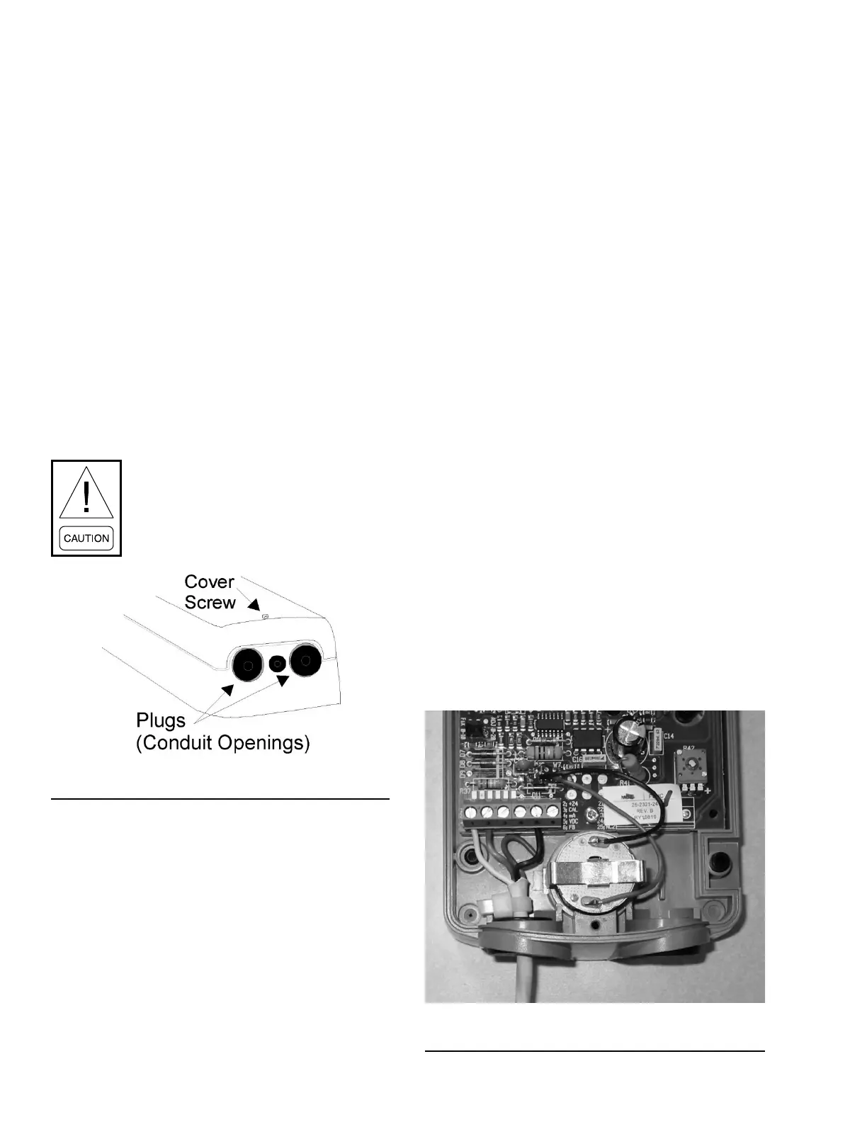
LD26865
FIGURE 7 - REMOVING THE ACTUATOR COVER
7. Hold the damper actuator in place, and evenly
hand tighten both clamp nuts onto the U-bolt. En-
sure the damper drive shaft remains in the fully
closed position while tightening the clamp nuts.
Secure the U-bolt to the damper drive shaft.
8. Press and hold the gear release. To verify that the
damper actuator rotates freely throughout the range,
rotate the drive coupler and drive shaft from fully
closed to fully open according to the steps below.
a. For horizontal LADK kits, rotate fully CW.
b. For vertical VADK kits, rotate fully CCW .
9. Loosen the damper actuator cover screw using a
#1 Phillips screwdriver, and remove the damper ac-
tuator cover. Push the plastic plug, adjacent to the
actuator terminal block, out of the conduit opening.
10. Use the #1 Phillips screwdriver to punch a center
hole through the plug, and reinsert the plug into
the opening.
A plenum-rated connection cable is provided, pre-
wired to the pressure control panel, for supply of
24 VAC power and 0–10 VDC signal voltage. The
cable is routed to the damper actuator through a
7/8-inch knock-out in the unit corner post.
11. Remove the knock-out, and insert the plastic
bushing provided in the low ambient damper kit.
Pull a sufcient length of cable through the bush-
ing to reach the connection terminal block at the
bottom of the actuator.
12. Push the cable through the hole in the plastic
conduit plug (enlarge if necessary), strip approxi-
mately 1 inch of the outer cable sheath, and con-
nect the wires to the following terminals:
• White = Terminal 1
• Red = Terminal 2
• Black = Terminal 5
• Green (if applicable) = not used
13. Secure the cable with a large nylon wire tie (pro-
vided) to prevent the cable from being acciden-
tally pulled from the damper actuator housing (see
Figure 8 on page 12).
LD26866
FIGURE 8 - CONNECTING CABLE TO TERMINALS

 Loading...