8
FORM 145.10-IOM4
ISSUE DATE: 2/27/2019
SECTION 1 - INSTALLATION
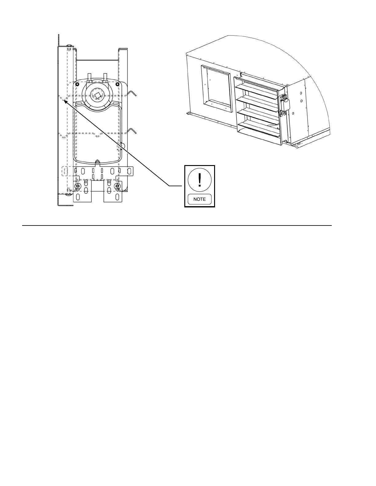
When damper blades are fully open, en-
sure they do not contact the unit.
LD26854 LD26855
FIGURE 2 - HORIZONTAL UNIT DAMPER
3. Position the damper casing between the two hori-
zontal ange surfaces, and butt the damper's drive
end against the vertical ange at the unit's cor-
ner. Ensure that the damper is orientated with the
drive shaft at the top of unit (see Figure 2 on page
8).
4. Position the damper blades to fully open and
check that there is no interference with unit. If the
damper blades contact the unit, adjust the damper
slightly away from the unit.
5. Secure the damper using the self-drilling screws
provided. Drive the screws through the holes in
the anges and into the metal damper casing.
6. Attach the remaining vertical ange opposite the
drive end of the casing.
7. Ensure that the damper assembly rotates freely,
with little or no resistance, by rotating the drive
shaft by hand.
DSV Vertical Units (B/C Style)
1. Locate the pilot holes at the condenser exhaust,
and line up the two vertical and two horizontal
duct anges accordingly. The VADK low ambi-
ent damper kit includes the factory-supplied duct
anges.
2. Secure the anges using self-drilling sheet metal
screws. Ensure the horizontal anges are ush
with the condenser exhaust opening.
3. Position the damper casing inside the anges and
secure with screws (see Figure 3 on page 9).
4. Position the damper blades to fully open and
check that there is no interference with the unit.
If the damper blades contact the unit, adjust the
damper slightly away from the unit.
5. Secure the damper using the self-drilling screws
provided. Drive the screws through the holes in
the anges and into the metal damper casing.
6. Attach the remaining vertical ange opposite the
drive end of the casing.
7. Ensure that the damper assembly rotates freely,
with little or no resistance, by rotating the drive
shaft by hand.