7
FORM 145.10-IOM4
ISSUE DATE: 2/27/2019
1
GENERAL INFORMATION
Before installing this accessory kit, turn
off electrical power to the equipment.
Failure to do so could result in electrical
shock, leading to component damage,
injury, or death.
If DSH/DSV unit operation is required at outdoor air
temperatures (OATs) between 50.0°F and 0.0°F (mini-
mum), install the optional low ambient damper kit to
maintain acceptable condensing pressure.
From the Commission > Standard menu on the Smart
Equipment controller (SEC), ensure the parameter CL-
GOATCUTOUT-EN is set to NO. This enables the unit
to operate when outdoor temperatures are below 45.0°F
(factory default).
In horizontal DSH units, install the damper directly
over the intake duct connection. In vertical DSV units,
install the damper over the exhaust duct connection.
Determine the damper actuator position by the refrig-
erant pressure. Depending on the output signal from a
proportional pressure control module, the direct-cou-
pled, electric damper actuator motor drives the damper
open or closed. A pressure transducer senses the high-
side refrigerant pressure through a service access port
that is located on the liquid refrigerant line leaving the
condenser. The pressure controller panel, complete
with terminal connection blocks for wiring, is attached
to a field-installed mounting bracket.
The low ambient damper kit provides all appropriate
mounting hardware for the pressure control module and
the damper actuator motor. The condenser corner panel
contains a routing hole near the damper actuator's mount-
ing location that enables installation of the plenum-rated
cable between the motor and the C450 controller.
On dual compressor units, the transducer
MUST be connected to the rst stage cir-
cuit liquid line tting. Connection to the
second stage refrigerant circuit can result
in system malfunction.
Prior to securing the damper to the unit,
ensure the damper blades do not interfere
with unit when fully open!
When installing the transducer, observe
all regulations governing the handling
and containment of hazardous or regulat-
ed materials (refrigerants or lubricants).
DAMPER INSTALLATION
FOR ALL DAMPERS: To avoid shipping
damage, the damper rod is recessed inside
damper and must be pulled out.
For damper information, refer to the DSV Installation,
Operation, and Maintenance (IOM) manual (145.29-
IOM3) or DSH IOM manual (145.32-IOM5).
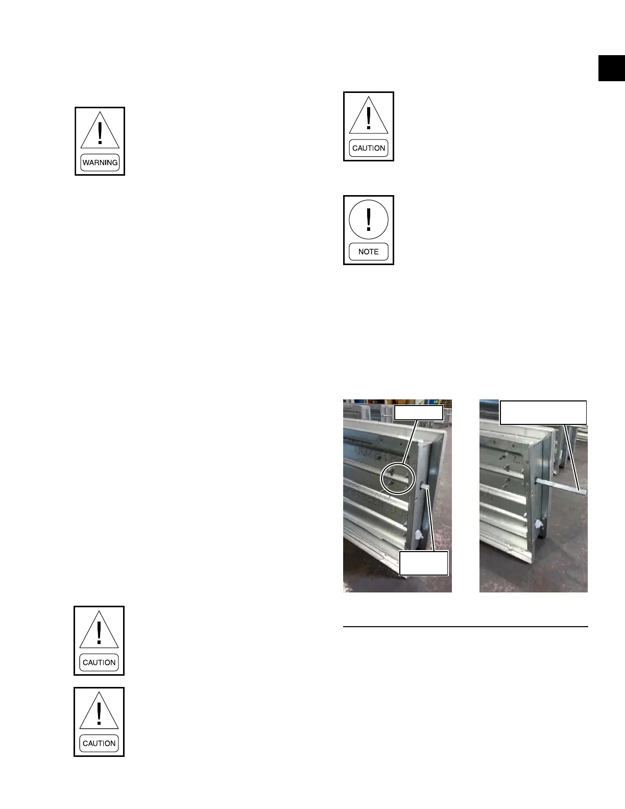
1. Loosen the four nuts as shown in Figure 1 below.
2. Slide out the damper rod approximately 3.5 inch-
es from the damper as shown in Figure 1.
3. Tighten the four nuts as shown in Figure 1.
Four nuts
Damper
Rod
Slide Out Damper
Rod 3.5 inches
LD26852 LD26853
FIGURE 1 - SLIDE OUT DAMPER ROD
DSH Horizontal Units (B/C Style)
1. Attach the two long, horizontal anges from the
LADK low ambient damper kit using the original
holes and screws. These flanges reduce the intake
opening height to match the damper dimensions.
2. Re-attach one of the original vertical anges as
close as possible to the edge of the corner post
(approximately 1/8 inch from corner post's edge).
SECTION 1 - INSTALLATION