16
RB SERIES ENGINEERING GUIDE
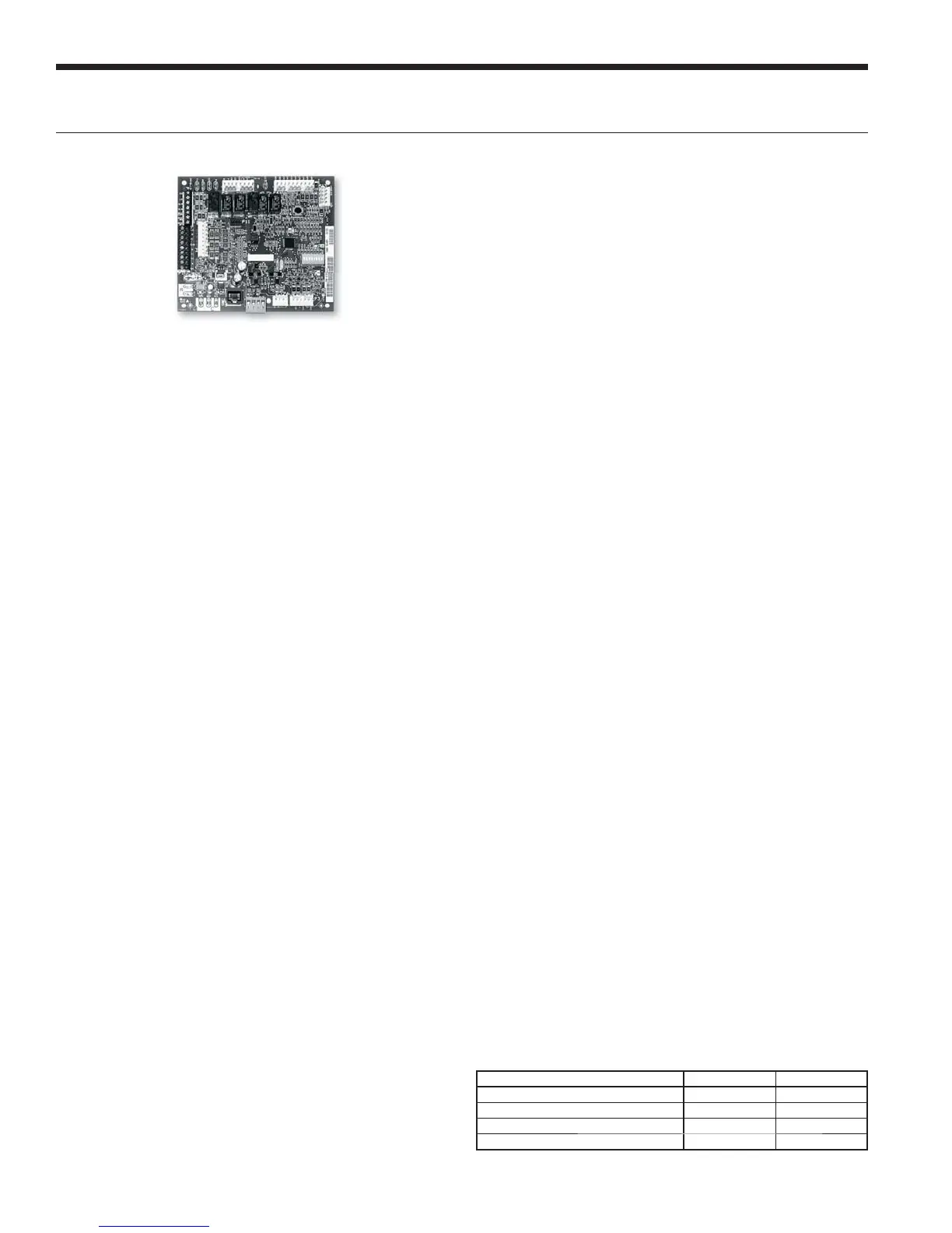
Aurora ‘Base’ Control
NOTE: Refer to the Aurora Base Control Application and
Troubleshooting Guide and the Instruction Guide: Aurora
Interface and Diagnostics (AID) Tool for additional information.
Control Features
oftware ABC Standard Version 3.0
Single or Dual Capacity Compressors
Either single or dual capacity compressors can be operated.
Variable Speed ECM
Blower Motor Option (If Applicable)
A Variable Speed ECM blower motor can be driven directly
using the onboard PWM output. Four blower speeds are
available based upon the G, Y1, Y2, and W input signals to
the board. The blower speeds can be changed either by the
ECM manual configurations mode method or by using the
Aurora AID Tool directly. All four blower speeds can be set
to the same speed if desired.
5-Speed ECM Blower Motor Option (If Applicable)
A 5-Speed ECM blower motor will be driven directly using
the thermostat connections. Any of the G, Y1, or Y2/W
signals can drive any of the 5 available pre-programmed
blower speeds on the motor. All 5 Series "G" vintage units
will be wired this way at the factory.
Other Control Features
• Random start at power up
• Anti-short cycle protection
• High and low pressure cutouts
• Loss of charge
• Water coil freeze detection
• Air coil freeze detection
• Over/under voltage protection
• Condensate overflow sensor
• Load shed
• Dehumidification (where applicable)
• Emergency shutdown
• Hot gas reheat operation (where applicable)
• Diagnostic LED
• Test mode push button switch
• Two auxiliary electric heat outputs
• Alarm output
• Accessory output with N.O. and N.C.
• Two Modbus communication Ports
Field Selectable Options via Hardware
DIP Switch (SW1) – Test/Configuration Button (See SW1
Operation Table)
Test Mode
The control is placed in the test mode by holding the push
button switch SW1 for 2 - 5 seconds. In test mode most of
the control timings will be shortened by a factor of sixteen
(16). LED3 (green) will flash at 1 second on and 1 second
off. Additionally, when entering test mode LED1 (red) will
flash the last lockout one time. Test mode will automatically
time out after 30 minutes. Test mode can be exited by
pressing and holding the SW1 button for 2 to 5 seconds or
by cycling the power. NOTE: Test mode will automatically
be exited after 30 minutes.
Variable Speed ECM Configuration Mode
(If Applicable)
The control is placed in the ECM configuration mode by
holding the pushbutton switch SW1 for 5 to 10 seconds, the
high, low, and “G” ECM speeds can be selected by following
the LED display lights. LED2 (yellow) will fast flash when
entering the ECM configuration. When setting “G” speed
LED3 (green) will be continuously lit, for low speed LED1
(red) will be continuously lit, and for high speed both LED3
(green) and LED1 (red) will be continuously lit. During the
ECM configuration mode LED2 (yellow) will flash each of
the 12 possible blower speeds 3 times. When the desired
speed is flashed press SW1, LED2 will fast flash until SW1
is released. “G” speed has now been selected. Next select
low speed, and high speed blower selections following the
same process above. After third selection has been made,
the control will exit the ECM configuration mode. Aux fan
speed will remain at default or current setting and requires
the AID Tool for adjustment.
Reset Configuration Mode
The control is placed in reset configuration mode by
holding the push button switch SW1 for 50 to 60 seconds.
This will reset all configuration settings and the EEPROM
back to the factory default settings. LED3 (green) will turn
off when entering reset configuration mode. Once LED3
(green) turns off, release SW1 and the control will reset.
DIP Switch (SW2)
SW2-1 FP1 Selection – Low water coil temperature limit
setting for freeze detection. On = 30°F; Off = 15°F.
SW2-2 FP2 Selection – On = 30°F; Off = N/A
SW2-3 RV – O/B - thermostat type. Heat pump
thermostats with “O” output in cooling or “B”
output in Heating can be selected. On = O; Off = B.
SW2-4 Access Relay Operation (P2)
and 2-5
Access Relay Operation SW2-4 SW2-5
Cycle with Blower ON ON
Cycle with Compressor OFF OFF
Water Valve Slow Opening ON OFF
Cycle with Comm. T-stat Hum Cmd OFF ON
Controls - Aurora Base Control