19
RB SERIES ENGINEERING GUIDE
Controls - Aurora Base Control cont.
CC2
EH1
Fac tory
Faul t
ALG
ALM
LS
ES
ACC c
Status
AURORA BASE
CONTROL™
RV – K1
CC2
CC – K2
CC Hi – K3
Fan – K4
Alarm – K5
Acc – K6
ACC no
ACC nc
O/B
C
R
LO
G
Y1
Y2
W
DH
3A-Fuse
O/B
C
R
LO
G
Y1
Y2
W
DH
LO
G
HI
CCG
CC
FG
F
R
HP
HP
LP
FP2
FP2
FP1
REV
REV
CFM
PWM
ECM PWM
Fac tory
Factory Fan Connection
RR
CC
C
RS 485
EH2
C
EH1
C
CO
(+)
(-)
R
C
RS485 Exp
Fac tory
Com1
Com2
Config
G
G
G
YR
SW1 Test
FP1 – 15
o
F/30
o
F
JW2 -
Alarm
P11
P5
P2
P1
P8
P7
P9
P6
P3
SW2
P13
P4
FP2 – 15
o
F/30
o
F
RV – B/O
ACC – Dip 4
ACC – Dip 5
CC – Dual/Single
L – Pulse/Continuous
Reheat/Normal
Factory Use
Field Connect ionsField Connect ions
C
LP
FP1
F
CC
G
Y1
1
2
3
4
5
6
7
8
Of f
On
N/A
RS485 NET
LED3
LED2LED1
Aurora Interface and Diagnostics (AID) Tool
The Aurora Interface and
Diagnostics (AID) Tool is
a device that is a member
of the Aurora network.
The AID Tool is used to
troubleshoot equipment
which uses the Aurora
control via Modbus RTU
communication. The AID
Tool provides diagnostics,
fault management, ECM
setup, and system configuration capabilities to the Aurora
family of controls. An AID Tool is recommended, although
not required, for ECM airflow settings. The AID Tool simply
plugs into the exterior of the cabinet in the AID Tool port.
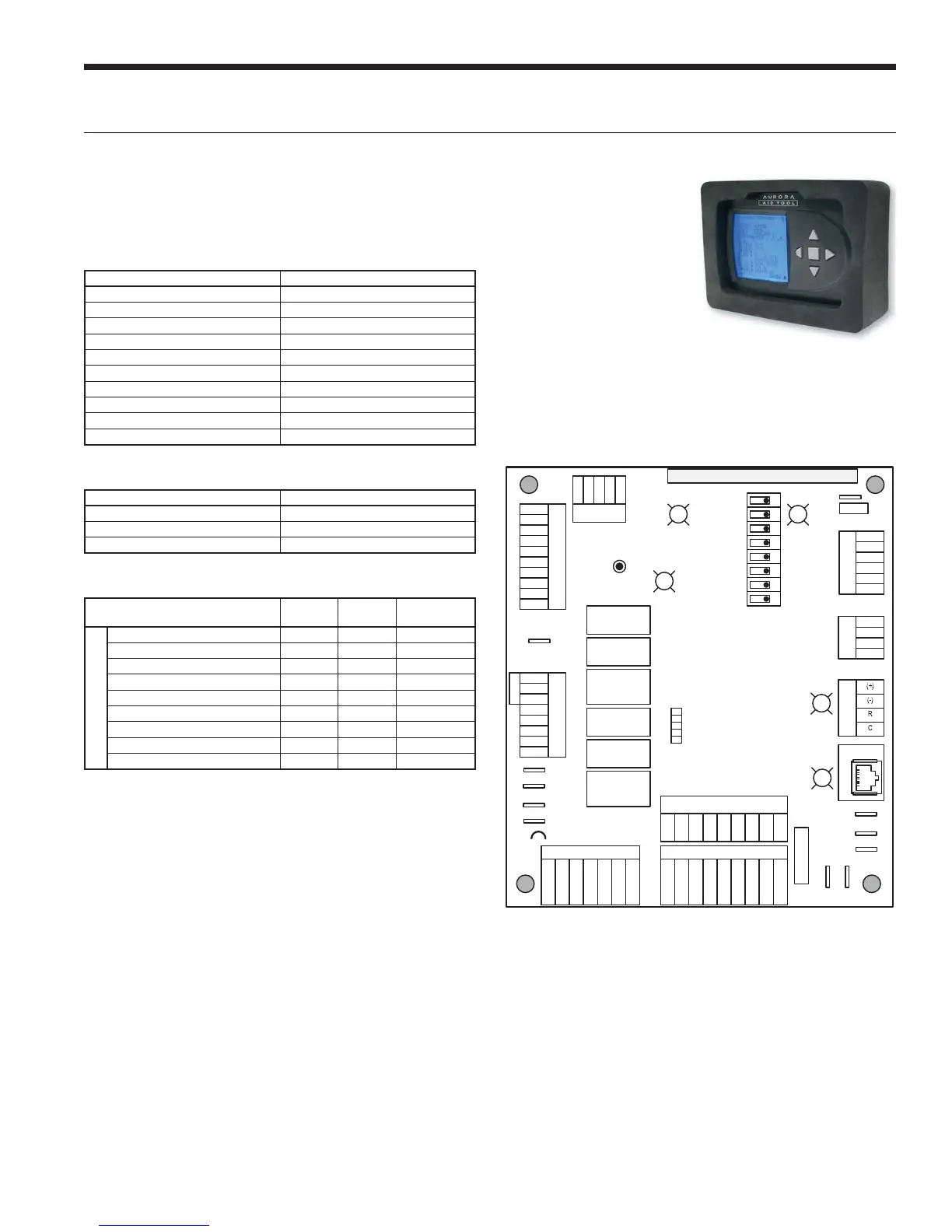
ABC Control Board Layout
Aurora ‘Base’ Control LED Displays
These three LEDs display the status, configuration, and
fault codes for the control. These can also be read in plain
English via the Aurora AID Tool.
Status LED (LED3, Green)
Description of Operation Fault LED, Green
Normal Mode ON
Control is Non-functional OFF
Test Mode Slow Flash
Lockout Active Fast Flash
Dehumidification Mode Flash Code 2
(Future Use) Flash Code 3
(Future Use) Flash Code 4
Load Shed Flash Code 5
ESD Flash Code 6
(Future Use) Flash Code 7
Configuration LED (LED2, Yellow)
Description of Operation Configuration LED, Yellow
No Software Overwritten Flashing ECM Setting
DIP Switch was Overwritten Slow Flash
ECM Configuration Mode Fast Flash
Fault LED (LED1, Red)
Red Fault LED
LED Flash
Code*
Lockout
Reset/
Remove
ABC Basic Faults
Normal - No Faults OFF –
Fault - Input 1 No Auto
Fault - High Pressure 2 Yes Hard or Soft
Fault - Low Pressure 3 Yes Hard or Soft
Fault - Freeze Detection FP2 4 Yes Hard or Soft
Fault - Freeze Detection FP1 5 Yes Hard or Soft
Fault - Condensate Overflow 7 Yes Hard or Soft
Fault - Over/Under Voltage 8 No Auto
Fault - FP1 & FP2 Sensor Error 11 Yes Hard or Soft
NOTE: All codes >11 use long flash for tens digit and short flash for the ones
digit. 20, 30, 40, 50, etc. are skipped.